72 Rockwell Automation Publication 1766-UM001O-EN-P - September 2021
Chapter 4 Communication Connections
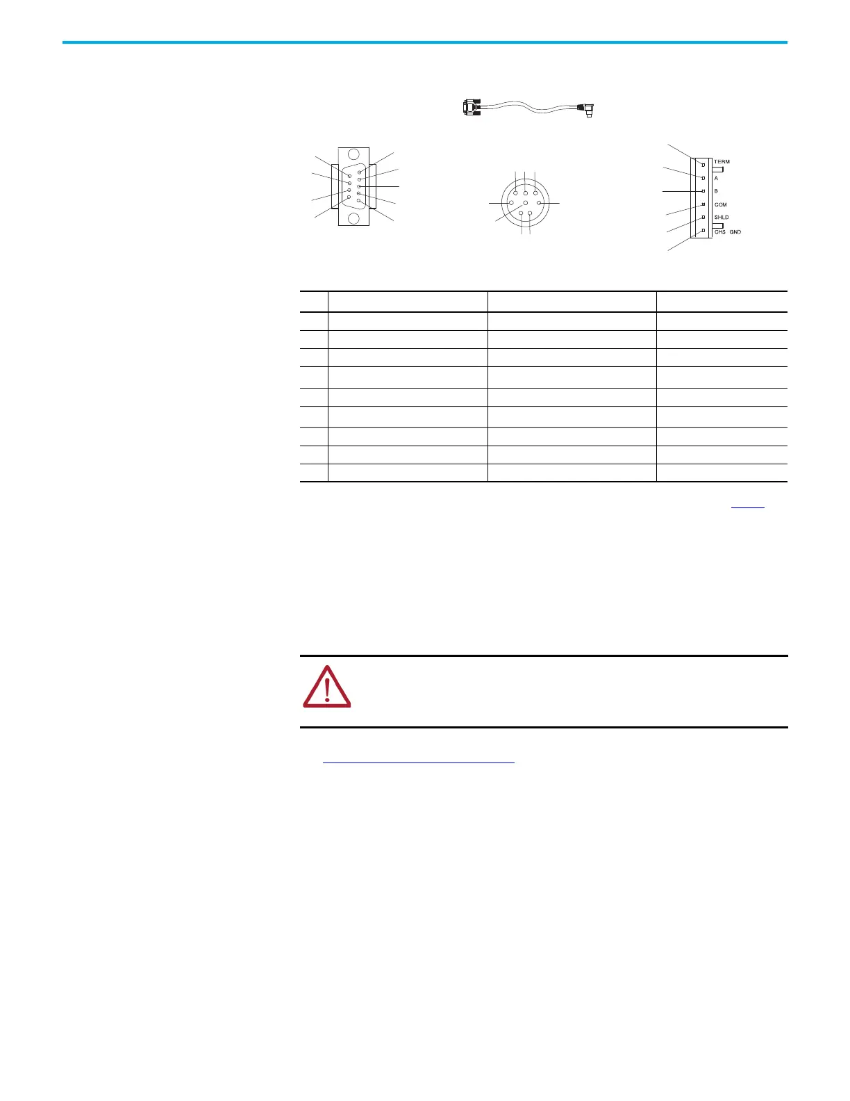
Figure 54 - Port Pinout
Safety Considerations
This equipment is suitable for use in Class I, Division 2, Groups A, B, C, D or
non-hazardous locations only.
See Safety Considerations
on page 20 for additional information.
Install and Attach the AIC+
1. Take care when installing the AIC+ in an enclosure so that the cable
connecting the MicroLogix controller to the AIC+ does not interfere with
the enclosure door.
2. Carefully plug the terminal block into the RS-485 port on the AIC+ you
are putting on the network. Allow enough cable slack to prevent stress on
the plug.
3. Provide strain relief for the Belden cable after it is wired to the terminal
block. This guards against breakage of the Belden cable wires.
Table 10 - Cable Assignment
Pin Port 1: DB-9 RS-232
Port 2
(1)
: (1761-CBL-PM02 cable)
(1) An 8-pin mini DIN connector is used for making connections to port 2. This connector is not commercially available. If you are
making a cable to connect to port 2, you must configure your cable to connect to the Allen-Bradley cable shown in Figure 54
.
Port 3: RS-485 Connector
1 Received line signal detector (DCD) 24V DC Chassis ground
2 Received data (RxD) Ground (GND) Cable shield
3 Transmitted data (TxD) Request to send (RTS) Signal ground
4
DTE ready (DTR)
(2)
(2) On port 1, pin 4 is electronically jumpered to pin 6. Whenever the AIC+ is powered on, pin 4 will match the state of pin 6.
Received data (RxD)
(3)
(3) In the 1761-CBL-PM02 cable, pins 4 and 6 are jumpered together within the DB-9 connector.
DH-485 data B
5 Signal common (GND) Received line signal detector (DCD) DH-485 data A
6
DCE ready (DSR)
(2)
Clear to send (CTS)
(3)
Termination
7 Request to send (RTS) Transmitted data (TxD) Not Applicable
8 Clear to send (CTS) Ground (GND) Not Applicable
9 Not Applicable Not Applicable Not Applicable
WARNING: EXPLOSION HAZARD
AIC+ must be operated from an external power source.
This product must be installed in an enclosure. All cables connected to the
product must remain in the enclosure or be protected by conduit or other means.
Port 1
DB-9 RS-232
Port 2
Cable straight D connector
Port 3
RS-485 connector
1761-CBL-AP00 or 1761-CBL-PM02
 Loading...


