CompactLogix Packaged Controllers 13
Publication 1769-IN082A-EN-P - July 2008
Panel Mount the System
To mount your system to a panel, complete these steps.
1. Using the assembled system as a template, carefully mark the center of all
mounting holes on the panel.
2. Remove the system and drill and tap the mounting holes for the
recommended M4 or #8 screws.
3. Place the grounding panel (if used) and CompactLogix system on the panel
to check for proper hole alignment.
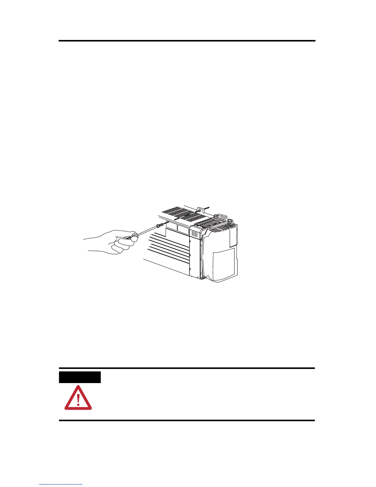
4. Insert the recommended screws into the mounting tabs on the packaged
controller and expansion modules (if used) and tighten.
DIN-rail Mount the System
To mount your system on a DIN rail, complete these steps.
The packaged controller can be mounted on these DIN rails:
• EN 50 022 - 35 x 7.5 mm (1.38 x 0.30 in.)
• EN 50 022 - 35 x 15 mm (1.38 x 0.59 in.)
1. Before mounting the packaged controller on a DIN rail, close the DIN-rail
latches.
ATTENTION
When this product is grounded through the DIN rail to chassis ground, use zinc plated
yellow-chromate steel DIN rail to assure proper grounding. The use of other DIN rail
materials (for example, aluminum or plastic) that can corrode, oxidize, or are poor
conductors, can result in improper or intermittent grounding. Secure DIN rail to
mounting surface approximately every 200 mm (7.8 in.) and use end-anchors
appropriately.

 Loading...


