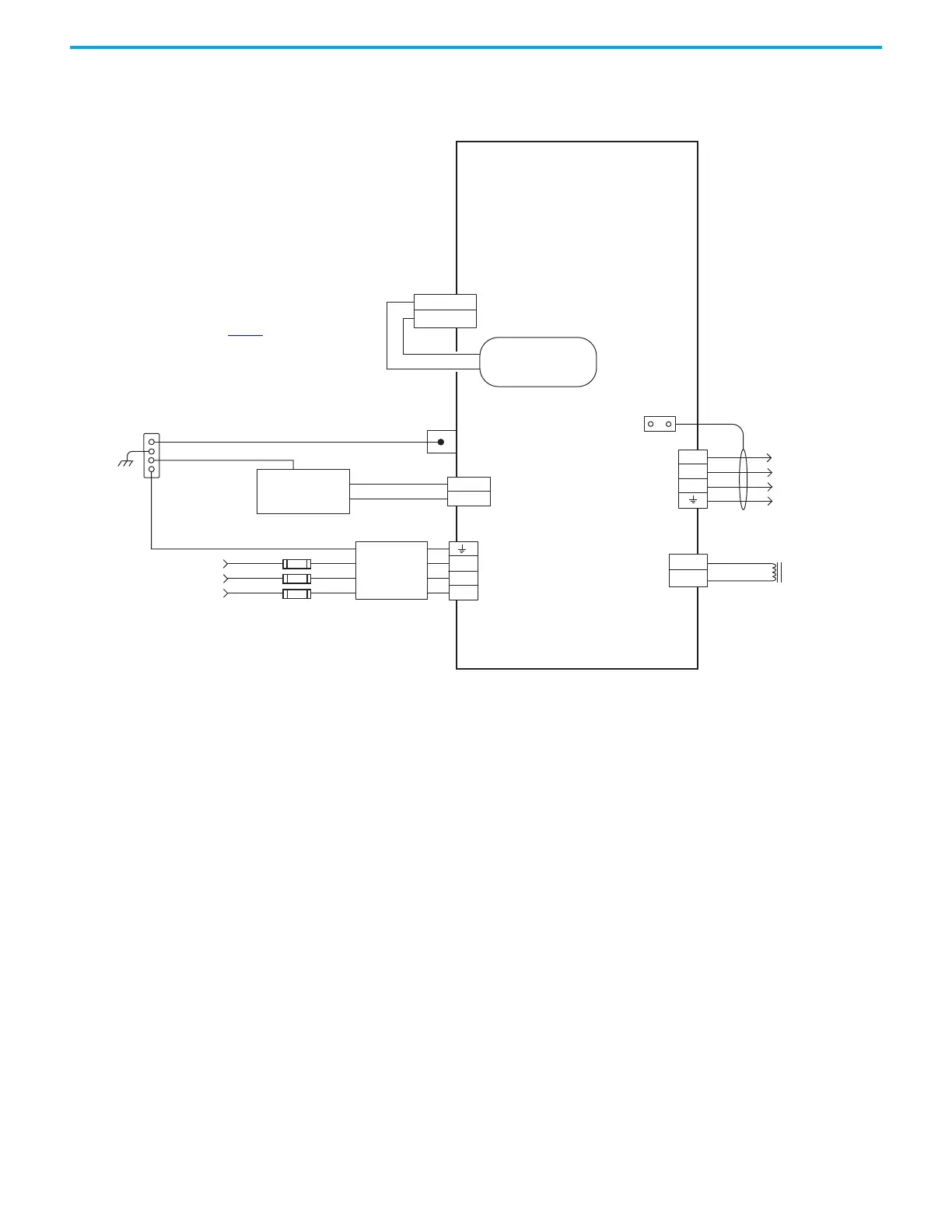
170…253V AC rms or
342…528V AC rms
Three-phase Input
Note 1
Bonded Cabinet Ground Bus *
Control Power
PE Ground
AC Input Power
Connector
Circuit Protection *
Note 2
* Indicates Customer Supplied Component
2198-C1004-ERS, 2198-C1007-ERS,
2198-C1015-ERS, 2198-C1020-ERS,
2198-C2030-ERS, 2198-C2055-ERS,
2198-C2075-ERS, 2198-C4004-ERS,
2198-C4007-ERS, 2198-C4015-ERS,
2198-C4020-ERS, 2198-C4030-ERS,
2198-C4055-ERS, 2198-C4075-ERS
Chassis
Note 4
Customer Supplied
+24V DC
Power Supply *
Motor Brake
Connector
Three-phase
Motor Power
Connections
Note 8
Motor Power
Connector
Cable Shield
Clamp
Refer to table on page 169
for note information.
Shunt
Connector
Motor Brake
Connections
2198-DBxxx-F
Three-phase
AC Line Filter
Note 3
Internal Shunt
Note 7
 Loading...