214 Rockwell Automation Publication 2080-UM002N-EN-E - November 2022
Chapter 10 Use the High-Speed Counter and Programmable Limit Switch
This bit can be cleared (0) by the control program and is also cleared by the HSC sub-system
whenever these conditions are detected:
• Low Preset Interrupt occurs
• Underflow Interrupt occurs
• Overflow Interrupt occurs
The Low Preset Interrupt status bit is set (1) when the HSC accumulator reaches the low preset
value and the HSC interrupt has been triggered. This bit can be used in the control program to
identify that the low preset condition caused the HSC interrupt. If the control program needs to
perform any specific control action based on the low preset, this bit would be used as
conditional logic.
This bit can be cleared (0) by the control program and is also be cleared by the HSC sub-
system whenever these conditions are detected:
• High Preset Interrupt occurs
• Underflow Interrupt occurs
• Overflow Interrupt occurs
When the HSC is in Counting mode, and PLS is enabled, this parameter indicates which PLS
element is used for the current HSC configuration.
The Error Codes detected by the HSC sub-system are displayed in this word. Errors include:
Writing to this element is not recommended except for clearing existing errors and to capture
new HSC errors.
Low Preset Interrupt (HSCSTS.LPCauseInter)
Description Data Format
HSC Modes
(1)
(1) For Mode descriptions, see HSC Mode (HSCAPP.HSCMode) on page 204.
User Program Access
HSCSTS.LPCauseInter bit 2…9 read/write
Programmable Limit Switch Position (HSCSTS.PLSPosition)
Description Data Format
HSC Modes
(1)
(1) For Mode descriptions, see HSC Mode (HSCAPP.HSCMode) on page 204.
User Program Access
HSCSTS.PLSPosition Word (INT) 0…9 read only
Error Code (HSCSTS.ErrorCode)
Description Data Format
HSC Modes
(1)
(1) For Mode descriptions, see HSC Mode (HSCAPP.HSCMode) on page 204.
User Program Access
HSCSTS.ErrorCode Word (INT) 0…9 read only
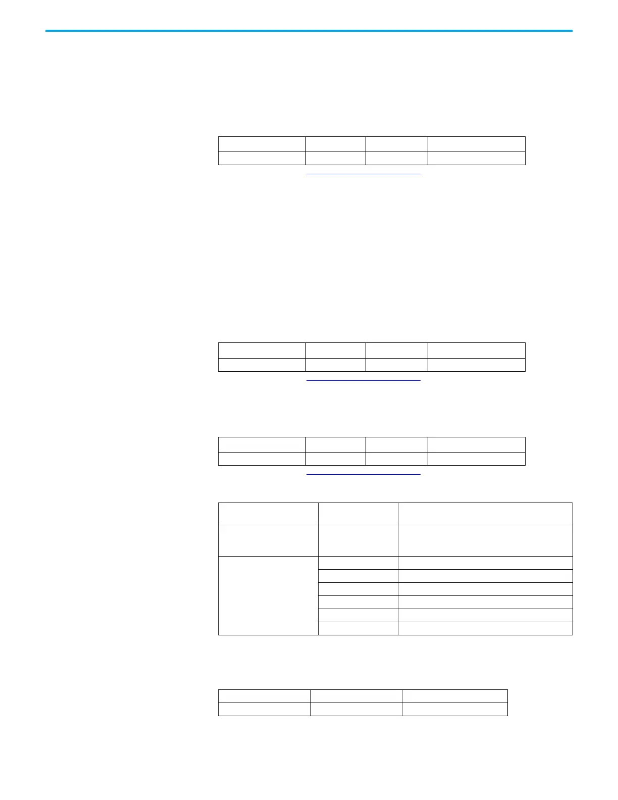
Error Code Sub-element
HSC Counting Error
Code
Error Description
Bit 15…8 (high byte) 0…255
The non-zero value for high byte indicates that the HSC
error is due to PLS data setting. The value of high byte
indicates which element of PLS data triggers the error.
Bit 7…0 (low byte)
0x00 No error
0x01 Invalid HSC counting mode
0x02 Invalid High preset
0x03 Invalid overflow
0x04 Invalid underflow
0x05 No PLS data
Accumulator (HSCSTS.Accumulator)
Description Data Format User Program Access
HSCSTS.Accumulator long word (32-bit INT) read only

 Loading...


