Rockwell Automation Publication 2080-UM002N-EN-E - November 2022 327
Appendix E PID Function Blocks
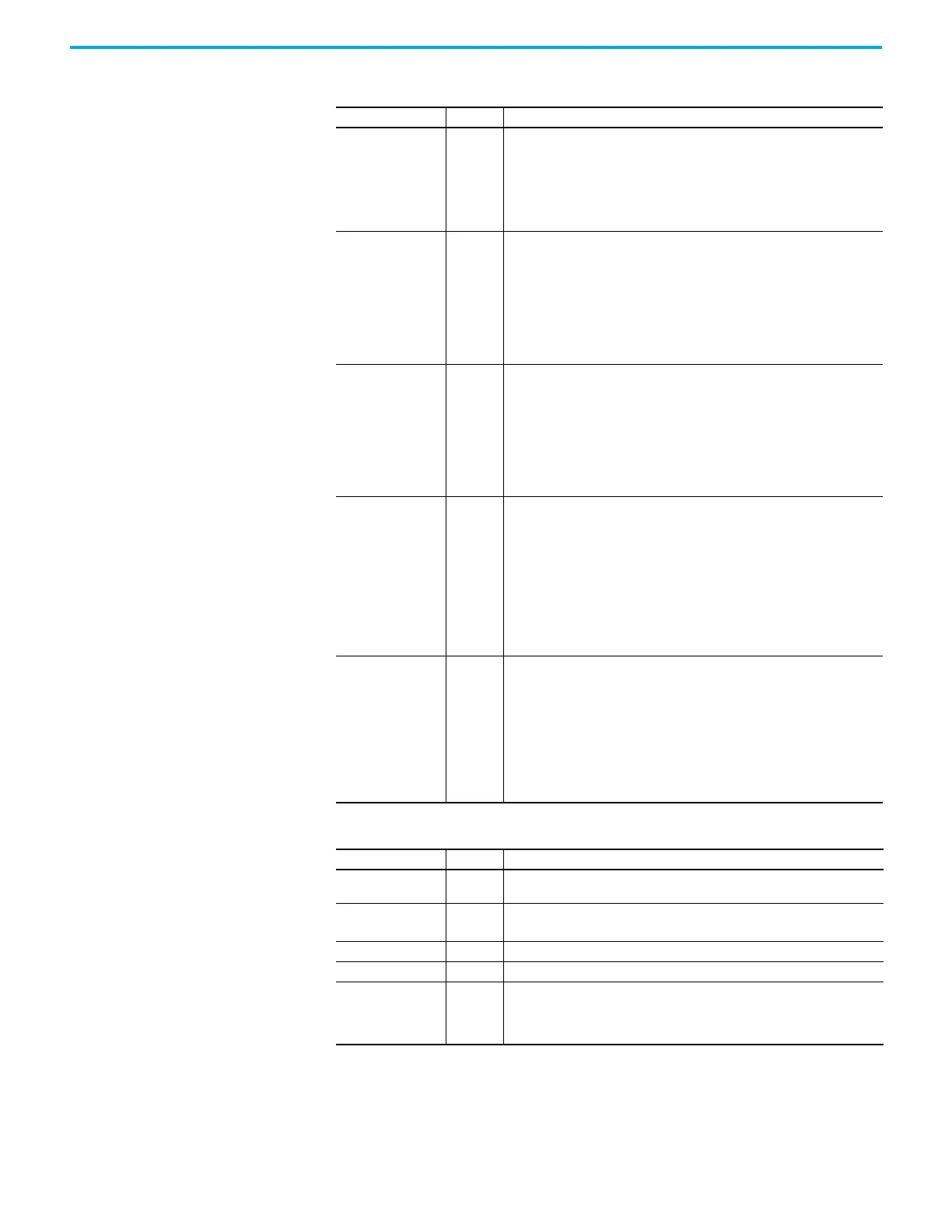
Table 87 - GAIN_PID Data Type
Parameter Type Description
DirectActing BOOL
Types of acting:
TRUE = Direct acting, output moves same direction as error. That is, the actual
process value is greater than the SetPoint and the appropriate controller
action is to increase the output. For example, Chilling.
FALSE = Reverse acting, output moves opposite direction as error. That is, the
actual process value is greater than the Setpoint and the appropriate
controller action is to decrease the output. For example, Heating.
ProportionalGain REAL
Proportional gain for PID (>= 0.0001).
Proportional gain for PID (P_Gain)
A higher proportional gain causes a larger change in the output based on the
difference between the PV (measured process value) and SV (set point value).
The higher the gain, the faster the error is decreased, but this may result in
instability such as oscillations. The lower the gain, the slower the error is
decreased, but the system is more stable and less sensitive to large errors. The
P_Gain usually is the most important gain to adjust and the first gain to adjust
while tuning.
TimeIntegral REAL
Time integral value for PID (>= 0.0001).
Time integral value for PID
A smaller integral time constant causes a faster change in the output based on
the difference between the PV (measured process value) and SV (set point
value) integrated over this time. A smaller integral time constant decreases the
steady state error (error when SV is not being changed) but increases the
chances of instability such as oscillations. A larger integral time constant
slows down the response of the system and make it more stable, but PV
approaches the SV at a slower rate.
TimeDerivative REAL
Time derivative value for PID (> 0.0).
Time derivative value for PID (Td)
A smaller derivative time constant causes a faster change in the output based
on the rate of change of the difference between PV (measured process value)
and SV (set point value). A smaller derivative time constant makes a system
more responsive to sudden changes in error (SV is changed) but increases the
chances of instability such as oscillations. A larger time constant makes a
system less responsive to sudden changes in error and the system is less
susceptible to noise and step changes in PV. TimeDerivative (Td) is related to
the derivative gain but allows the derivative contribution to PID to be tuned
using time so the sample time must be taken into consideration.
DerivativeGain REAL
Derivative gain for PID (>= 0.0).
Derivative gain for PID (D_Gain)
A higher derivative gain causes a larger change in the output based on the rate
of change of the difference between the PV (measured process value) and SV
(set point value). A higher gain makes a system more responsive to sudden
changes in error but increases the chances of instability such as oscillations. A
lower gain makes a system less responsive to sudden changes in error and
makes the system less susceptible to noise and step changes in the PV.
If derivative gain is set to zero, it disables the derivative portion of the
PID.
Table 88 - AT_Param Data Type
Parameter Type Description
Load REAL
Load parameter for auto tuning. This is the output value when starting
AutoTune.
Deviation REAL
Deviation for auto tuning. This is the standard deviation used to evaluate the
noise band needed for AutoTune (noise band = 3* Deviation)
(1)
(1) The application engineer can estimate the value of ATParams.Deviation by observing the value of Process input. For example,
in a project that involves the control of temperature, if the temperature stabilizes around 22 °C, and a fluctuation of
21.7…22.5 °C is observed, the value of ATParams.Deviation will be (22.5…21.7)/2=0.4.
Step REAL Step value for AutoTune. Must be greater than noise band and less than ½ load.
ATDynamSet REAL Waiting time in seconds before abandoning auto tune.
ATReset BOOL
Determines whether the output value is reset to zero after an AutoTune
sequence:
TRUE = Reset output to zero.
FALSE = Leaves output at Load value.
 Loading...


