358 Rockwell Automation Publication 2080-UM002N-EN-E - November 2022
Appendix H User-defined Function Block Motion Instructions
Example Configuration with Position Units
The E-gear ratio (KNX5100C -> Function List -> E-gear Ratio) is always used to provide a
representation of positioning (units or counts) or to define a Pulse-Pulse Following
relationship (MAG/PT). When the E-gear ratio is changed, the positioning of the drive is
changed. When not using the MAG or PT operation mode, the E-gear ratio is used to define
position scaling.
When Operating Units = 1, Position Units are used, and we can define application units instead
of using drive counts. In KNX5100C software, the E-gear ratio is defined to provide Position
scaling. This is encoder counts (or pulses)/motor rotation.
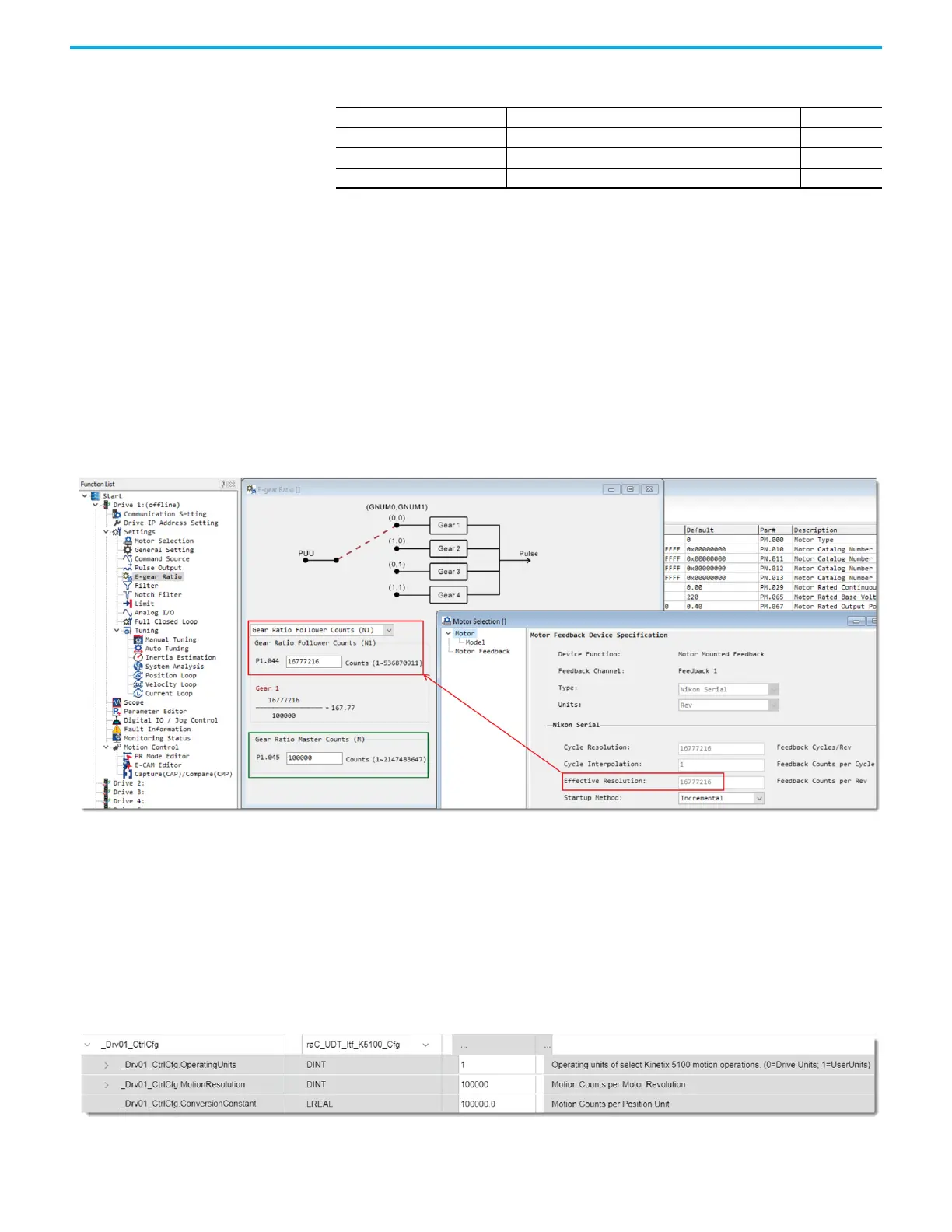
By using KNX5100C software, navigate to Settings -> E-gear Ratio.
Figure 38 - Position Units Configuration
All Position Unit configurations must:
• Configure GearRatioFollowerCounts ID151 (P1.044) to be the same as the motor feedback
effective resolution.
• Configure GearRatioMasterCounts ID152 (P1.045) to provide motor feedback counts/
motor rotation.
• You define this value and can be any count value, default values with high-resolution
encoders are 100,000 counts/motor rotation. The E-gear configuration is used with the
Device Object Cfg tags.
Figure 39 - Position Units Configuration Tag
Table 103 - raC_UDT_Itf_K5100_Cfg Data Types
Member Description Data Type
OperatingUnits 0 = Drive Units; 1 = UserUnits DINT
MotionResolution Motion Counts per Motor Revolution DINT
ConversionConstant Motion Counts per Position Unit LREAL

 Loading...


