36 Rockwell Automation Publication 2080-UM002N-EN-E - November 2022
Chapter 2 About Your Controller
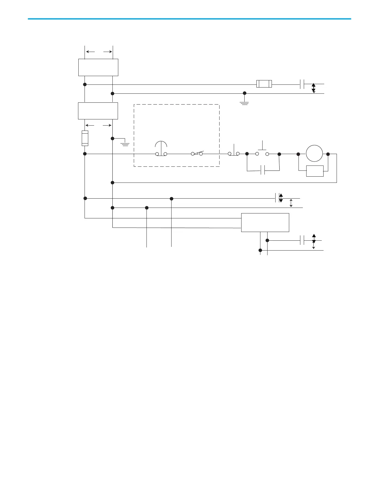
Figure 2 - Schematic – Using ANSI/CSA Symbols
Emergency-stop
push button
230V AC
Operation of either of these contacts will remove
power from the external I/O circuits, stopping
machine motion.
Fuse
MCR
Fuse
MCR
MCR
MCR
Stop
Start
Line terminals: Connect to terminals of power supply
Line terminals: Connect to 24V DC terminals of power supply.
230V AC
output
circuits
Disconnect
Isolation
transformer
115V AC or 230V AC
I/O circuits
L1
L2
Master Control Relay (MCR)
Cat. No. 700-PK400A1
Suppressor
Cat. No. 700-N24
(Lo)
(Hi)
DC power supply. Use NEC
Class 2 for UL Listing.
X1 X2
115V AC or
230V AC
_
+
MCR
24 V DC
I/O circuits
Suppr.
Overtravel limit
switch

 Loading...


