36 Rockwell Automation Publication 2711P-UM008I-EN-P - February 2022
Chapter 2
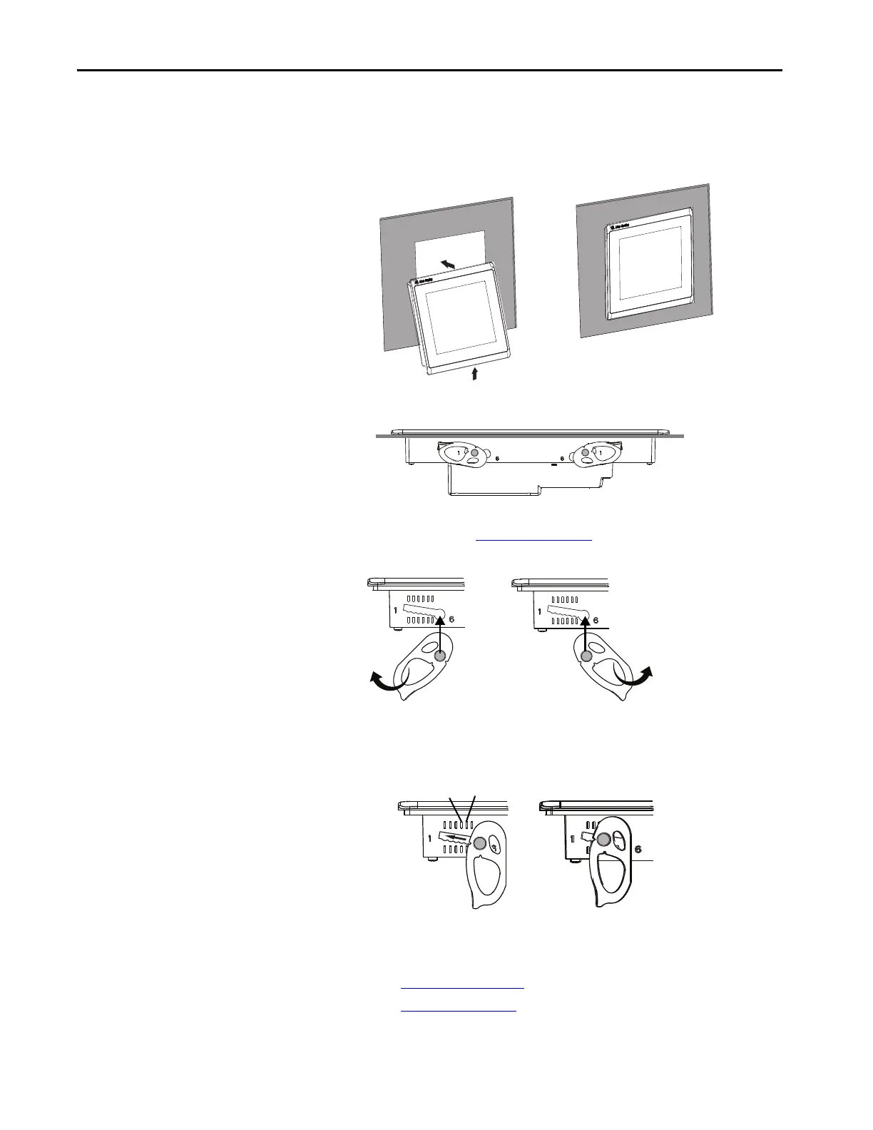
b. Tilt the terminal into the panel cutout and guide upward into the
cutout so that the levers are behind the panel.
c. Pull the top of the terminal toward you to verify that the levers are
still in place and the terminal is stabilized in the panel.
d. Insert the remaining levers in the slots by using the orientations for
your terminal in Figure 3 on page 34
.
The direction that you rotate the levers varies for each terminal size.
4. Slide and rotate each lever to a notch that is one or two positions greater
than the final lock position, starting with the first lever in the sequence.
For example, if the final lock position is 3, slide the lever to notch 4 or 5.
a. See Figure 15 on page 31
to get the final lock position of the levers.
b. See Figure 3 on page 34
to get the locking sequence.
TIP The levers help to prevent the terminal from falling out of the panel.
TIP Use the alignment marks or previous marks you made on the bezel
to help position the levers and identify the final slot position.

 Loading...


