20 Rockwell Automation Publication 750-AT006D-EN-P - January 2022
Chapter 1 Background
This type of control structure has the following advantages:
• Precise control of position, velocity, and torque
• Flexibility to switch between position, velocity, and torque modes without changing tuning gains
• Simple Manual Tuning
Flux Vector mode can operate in these configurations:
• Torque control: Only the torque loop is enabled
• Velocity control: Only velocity and torque loops are enabled
• Position control: Position, velocity, and torque loops are all enabled
Each loop and their internal functions are described in the following sections:
• Position Loop
on page 20
• Velocity Loop on page 21
• Torque Loop on page 25
Position Loop
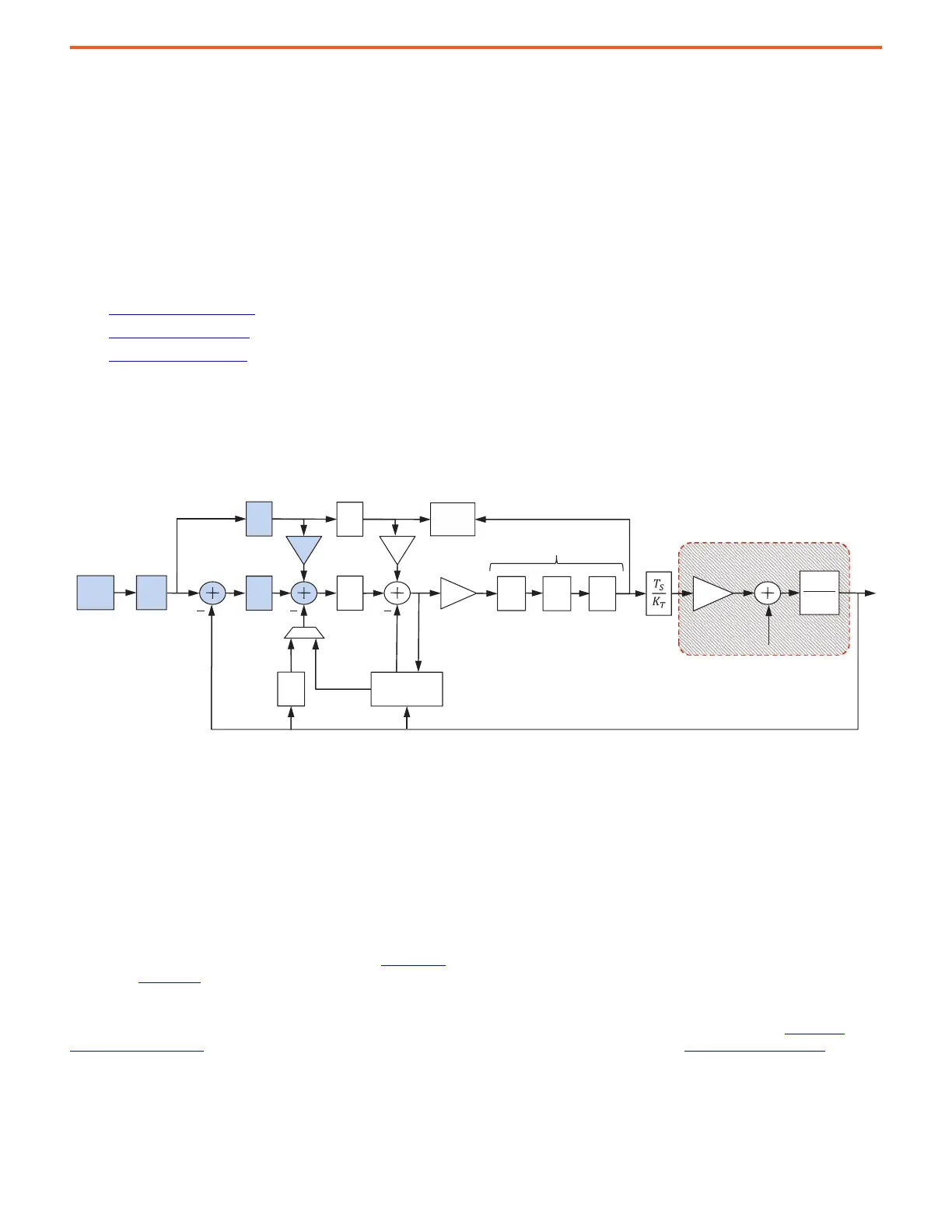
The position loop consists of position reference, reference notch filters, and position regulator sections.
Figure 18 - Position Loop
The position, velocity, and torque loops are all enabled in Position mode. Elements of the position loop are summarized:
Position Reference (P
REF
) – The position reference can come from various sources. The position reference source is selected by position,
velocity, and torque mode parameters 10:30…10:33:
• Network Communication from Logix Controller – position direct mode
• Internal PTP planner – point-to-point Position mode
• Encoder Position Reference
• Internal PCAM planner - Position CAM
• Internal PLL planner - Position Phase Locked Loop
See the PowerFlex 750 Reference Manual, publication 750-RM002
, and PowerFlex Drives with TotalFORCE® Control Programming Manual,
publication 750-PM100, for more information.
Reference Notch Filters (RN) – Two reference notch filters are placed on command signals to remove load-side resonances and vibration
that is common in, robots, cranes, cantilevered loads, liquid sloshing, laser cutting, and material handling applications. See Load Side
Resonances on page 14 for more information. These filters are capable of adjustable width and depth. See Notch Filters on page 46 for more
information.
Position Regulator (P
REG
) – The position regulator consists of a proportional-integral (PI) controller. In legacy PowerFlex 755 drives, K
PP
is in
parallel with K
PI
. Here, legacy K
PP
10:839 [Psn Reg Kp] is the position loop bandwidth in units of [rad/sec] and legacy K
PI
10:838 [Psn Reg Ki]
2
1
sJ
T
PI
s
PI
s
Fs
K
T
P
REG
V
REG
Velocity
Feedback
Filter
Position
Feedback
Velocity
Estimate
Feed
Forwards
Kvff Kaff
Position
Command
LP
LL
N
Torque Loop Filters
Load Torque
Load
Observer
K
J
Torque
Estimate
Adaptive
Tuning
RN
System Under Control
P
REF
 Loading...


