40 Rockwell Automation Publication 750-AT006D-EN-P - January 2022
Chapter 2 Product Features
Resonances are characterized in the following way:
• High frequency (HF) resonances are above the low frequency limit, 10:2112 [Trq NF Freq LLim]
• Low frequency (LF) resonances are below the low frequency limit, 10:2112 [Trq NF Freq LLim]
• Mid frequency (MF) resonances are HF resonances that are slightly above the low frequency limit, 10:2112 [Trq NF Freq LLim]
Adaptive Tuning Modes
The following sections describe each adaptive tuning configuration mode in detail:
• Disabled
• Tracking Notch on page 41
• Gain Stabilization on page 42
• Tracking Notch and Gain Stabilization on page 43
• Gain Optimization on page 44
Disabled
10:2110 [AdptTune Config] = Disabled (0) – Adaptive tuning is always running in the background to identify motor side resonances, even when
the feature is disabled. However, no action is taken to compensate for identified resonances in this mode. The result is status only, which
allows you react to changes manually or with custom logic. This mode is useful for condition monitoring, diagnostics, and preventative
maintenance purposes in tracking HF resonances that change over time. Parts of the control loop structure that are affected by this mode
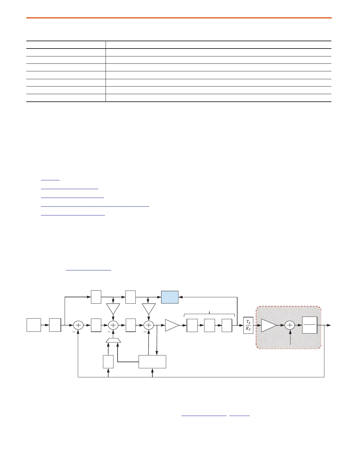
are highlighted in Figure 37 on page 40
.
Figure 37 - Disabled Configuration
When an HF resonance with a center frequency between 10:2112 [Trq NF Freq LLim] and 10:2113 [Trq NF Freq HLim] is detected with a
magnitude above 10:2111 [Trq NF Threshold], the resonance's center frequency and magnitude are measured and placed in 10:2123 [Trq NF
Freq Est] and 10:2124 [Trq NF Mag Est], respectively. A suitable notch filter width is also calculated and placed in 10:2125 [Trq NF Wdth Est] by
interpolating a value between 10:2114 [Trq NF WidthMin] and 10:2115 [Trq NF WidthMax] based on the location of 10:2123 [Trq NF Freq Est]
between 10:2112 [Trq NF Freq LLim] and 10:2113 [Trq NF Freq HLim]. See Figure 35 on page 35
. Figure 38 shows the frequency response of an
example resonance to illustrate how it is identified.
Table 15 - Adaptive Tuning Reset Behavior
Parameter When Reset to Default Value
Torque Notch Filter Frequency Estimate Transition out of Tracking Notch mode or Tracking Notch with Gain Stabilization mode
Torque Notch Filter Magnitude Estimate When a resonance is not identified
Torque Low Pass Filter Bandwidth Actual Transition out of Gain Stabilization mode or Tracking Notch with Gain Stabilization mode
Adaptive Tuning Gain Scaling Factor Transition to Disabled or Tracking Notch Filter modes
Adaptive Tuning Stability Frequency Transitions out of Gain Stabilization mode, Tracking Notch with Gain Stabilization mode, or Gain Optimization mode
Adaptive Tuning Stability Magnitude Transitions out of Gain Stabilization mode, Tracking Notch with Gain Stabilization mode, or Gain Optimization mode
Gain Optimization Error Maximum Transitions out of Gain Optimization mode
2
1
sJ
T
PI
s
PI
s
Fs
K
T
P
REG
V
REG
Velocity
Feedback
Filter
Position
Feedback
Velocity
Estimate
Feed
Forwards
Kvff Kaff
Position
Command
LP
LL
N
Torque Loop Filters
Load Torque
Load
Observer
K
J
Torque
Estimate
Adaptive
Tuning
RN
System Under Control
P
REF
 Loading...


