Rockwell Automation Publication 750-AT006D-EN-P - January 2022 47
Chapter 2 Product Features
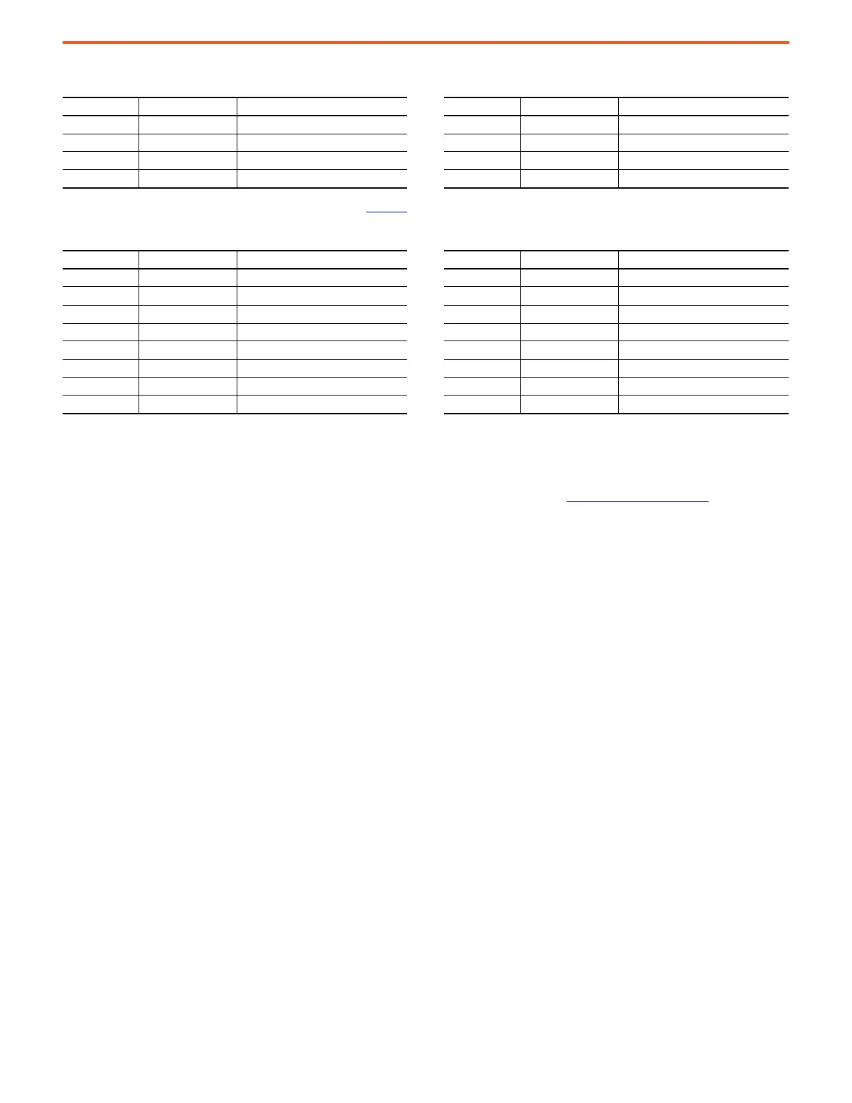
Corresponding torque notch filter parameters are given in Table 18.
Configuration
Notch filters have four modes of operation depending on the gain K setting, similar to lead-lag filters. The difference is that notch filters can
only be configured as second order and lead-lag filters can only be configured as first order. See Lead Lag Filters on page 52 for more
information.
The filter is disabled when F = 0 Hz, regardless of the other settings.
Configured as a Notch Filter (K = 1)
When K = 1, the notch filter operates as a second order notch filter. This is the recommended and default mode of operation. Also, adaptive
tuning sets K =1 when tracking a notch filter.
The variable width and depth functionality of the notch filter provides more flexibility in achieving high performance in some situations. The
width can be increased, which allows one filter to suppress two HF resonances that are close to each other. An increased width is also
effective in suppressing a resonance that slightly moves as mechanics slowly degrade over time. This reduces the need for retuning. The
width of a torque notch filter can be decreased to suppress an MF resonance that is near the closed loop bandwidth. This minimizes the
impact of the filter’s phase lag on stability margin and reduces the need for detuning. The depth can be adjusted only as deep as required to
suppress resonances with magnitudes large and small. This also conserves phase and allows for higher tuning performance.
The recommended range for width Z
W
is from a minimum width of 0 to a maximum width of 4. The default width Z
W
= 0.707 produces
relatively good performance across applications.
The recommended range for depth Z
D
is from a maximum depth of 0 to a minimum depth of < Z
W
. The default depth Z
D
= 0 provides
maximum notch attenuation. Also, adaptive tuning sets Z
D
= 0 when tracking a notch filter. Note that the filter is off when K = 1 and Z
D
= Z
W
or when F = 0. Furthermore, the filter becomes an inverse notch (generating resonance) when Z
D
> Z
W
.
Notch filter width can be approximated in units of [Hz] as the range of frequencies impacted by the filter between -3 dB points.
Notch filter depth can be calculated in units of [dB] at the center frequency of the filter.
Table 17 - Reference Notch Filter Parameters
Parameter No. Parameter Name Description Parameter No. Parameter Name Description
10:942 [Ref NF1 Freq] Reference Notch Filter 1 Frequency 10:948 [Ref NF2 Freq] Reference Notch Filter 2 Frequency
10:943 [Ref NF1 Width] Reference Notch Filter 1 Width 10:949 [Ref NF2 Width] Reference Notch Filter 2 Width
10:944 [Ref NF1 Depth] Reference Notch Filter 1 Depth 10:950 [Ref NF2 Depth] Reference Notch Filter 2 Depth
10:945 [Ref NF1 Gain] Reference Notch Filter 1 Gain 10:951 [Ref NF2 Gain] Reference Notch Filter 2 Gain
Table 18 - Torque Notch Filter Parameters
Parameter No. Parameter Name Description Parameter No. Parameter Name Description
10:2159 [Trq NF1 Freq] Torque Notch Filter 1 Frequency 10:2179 [Trq NF3 Freq] Torque Notch Filter 3 Frequency
10:2161 [Trq NF1 Width] Torque Notch Filter 1 Width 10:2181 [Trq NF3 Width] Torque Notch Filter 3 Width
10:2163 [Trq NF1 Depth] Torque Notch Filter 1 Depth 10:2183 [Trq NF3 Depth] Torque Notch Filter 3 Depth
10:2165 [Trq NF1 Gain] Torque Notch Filter 1 Gain 10:2185 [Trq NF3 Gain] Torque Notch Filter 3 Gain
10:2169 [Trq NF2 Freq] Torque Notch Filter 2 Frequency 10:2189 [Trq NF4 Freq] Torque Notch Filter 4 Frequency
10:2171 [Trq NF2 Width] Torque Notch Filter 2 Width 10:2191 [Trq NF4 Width] Torque Notch Filter 4 Width
10:2173 [Trq NF2 Depth] Torque Notch Filter 2 Depth 10:2193 [Trq NF4 Depth] Torque Notch Filter 4 Depth
10:2175 [Trq NF2 Gain] Torque Notch Filter 2 Gain 10:2195 [Trq NF4 Gain] Torque Notch Filter 4 Gain
Width Hz 2FZ
W
1z
2
– 0.5z
4
– z
6
–z,
Z
D
Z
W
--------==
Depth dB 20 10
Z
D
Z
w
-------
log=
 Loading...


