46 Rockwell Automation Publication 750-AT006D-EN-P - January 2022
Chapter 2 Product Features
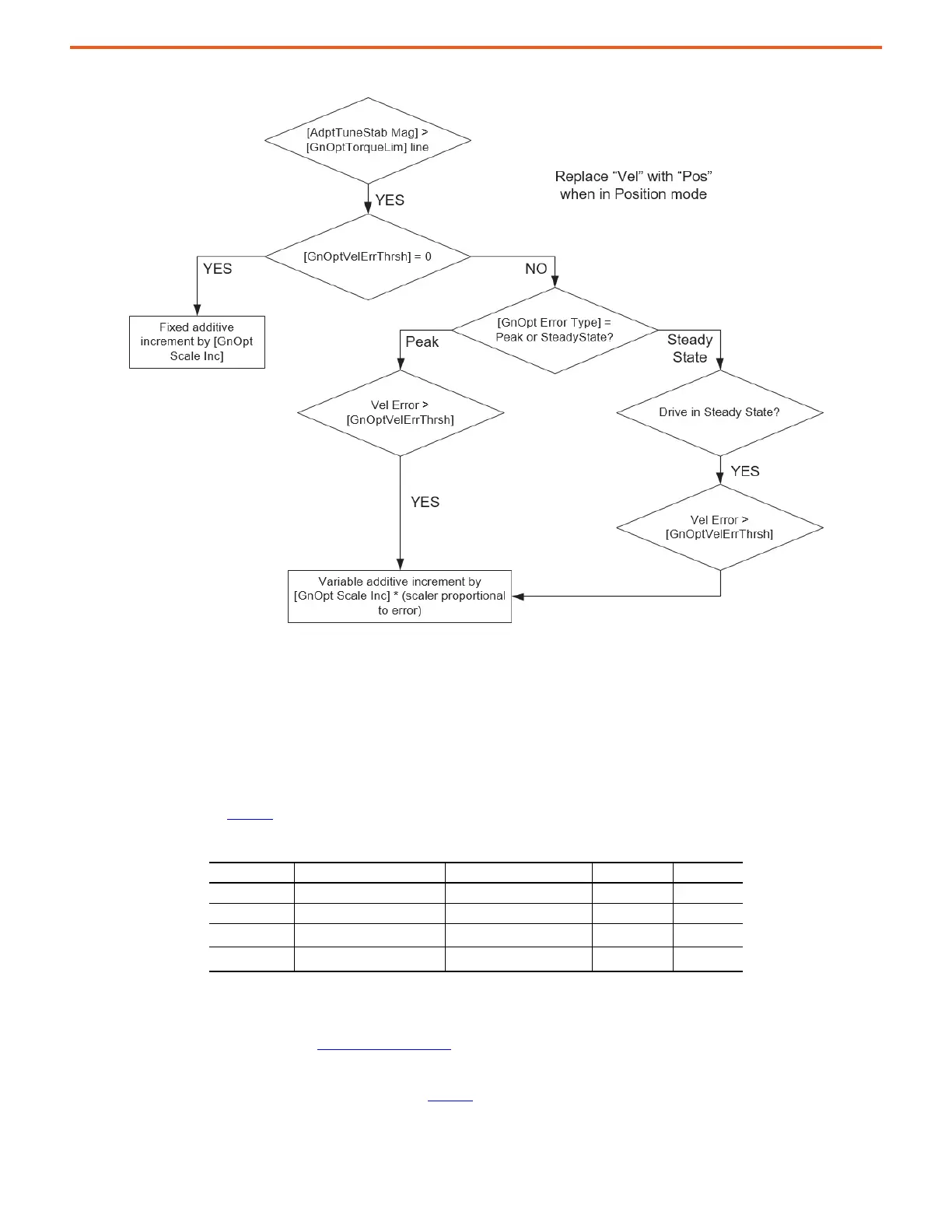
Figure 46 - Gain Optimization Flowchart
Notch Filters
Notch filters are represented by the following second order transfer function.
Coefficients are defined in Table 16
. They feature variable adjustment of width, depth, and gain to allow for a wide range of applications.
There are four torque notch filters in the drive. There are two position reference notch filters, two velocity reference notch filters, and two
process PID reference notch filters in the drive. These three sets of reference notch filters share common parameters, which allow all
command signals to be affected uniformly. The torque notch filters suppress MF and HF motor side resonances and the reference notch
filters suppress load side resonances. See Resonances
on page 12 for more information on the various types of resonances and how to
suppress them.
Corresponding reference notch filter parameters are given in Table 17
.
Table 16 - Variable Notch Filter Parameters
Parameter Name Minimum Maximum Default
F Notch Filter Frequency 0 Hz 3999 Hz 0 Hz
K Notch Filter Gain -20 20 1.0
Z
W
Notch Filter Width 0 = minimum width
10
4
0.707
Z
D
Notch Filter Depth 0 = maximum depth
10
4
0
Gs
K
2
s
2
2KZ
D
2Fs 2F
2
++
s
2
2Z
W
2Fs 2F
2
++
-------------------------------------------------------------------------------------------- K
2
s
2
2Z
D
2F
D
s 2F
D
2
++
s
2
2Z
W
2Fs 2F
2
++
-----------------------------------------------------------------------------------------
K,
F
F
D
------- -
== =
 Loading...


