Rockwell Automation Publication 750-AT006D-EN-P - January 2022 85
Chapter 6 Active Front End Tuning
Table 27 summarizes the source selection parameter.
The bandwidth of the voltage regulator determines how fast the voltage regulator will respond during transient conditions. To ensure
complete decoupling of the current control loop and the voltage control loop, a loop spacing between the voltage regulator bandwidth and
the current regulator bandwidth of 1:10 is recommended. Loop spacing can be reduced to 1:5 in certain applications where very large DC bus
capacitance is connected to the bus or in the case of a very large source impedance.
Active Damping
Active damping is an additional control that helps attain proper converter operation, especially at relatively high B
W
settings for the voltage
and current control loops and a high source impedance. The main function of active damping is to help alleviate resonance conditions
caused by the interaction between the converter control loops and the LCL filter. This is done by mathematically creating a virtual resistance
in series with the AC filter capacitor.
In other applications where resonance conditions occur because of the existence of nonlinear loads on the same point of common coupling.
These nonlinear loads, such as diode/thyristor-based rectifiers, can cause notching on the lines and become a source of higher-order
harmonics such as 5
th
, 7
th
, 11
th
, and so on. In some of these applications, if the resonance current in the AC capacitors is relatively high, it
can be beneficial to reduce the active damping gain while reducing the time constant of the feed forward voltage components (see page 86).
Table 28 explains 13:81 [Actv Damping Gn], which lets you adjust the active damping gain.
Disturbance Rejection
The primary reason for the disturbance rejection function is to compensate for any sudden load disturbances by either measuring or
estimating load changes. The corresponding active current component can be calculated and used as a feed forward component to the
current control loop. Using the disturbance rejection functions results in an excellent dynamic performance even at relatively low B
W
settings of the current and voltage regulators. This is achieved by using two main functions, the feed forward power and the DC bus
observer, which are configured using 13:300 [PwrFeedFwdConfig] and 13:320 [BusObsConfig]. Table 29
explains the parameters for these
functions.
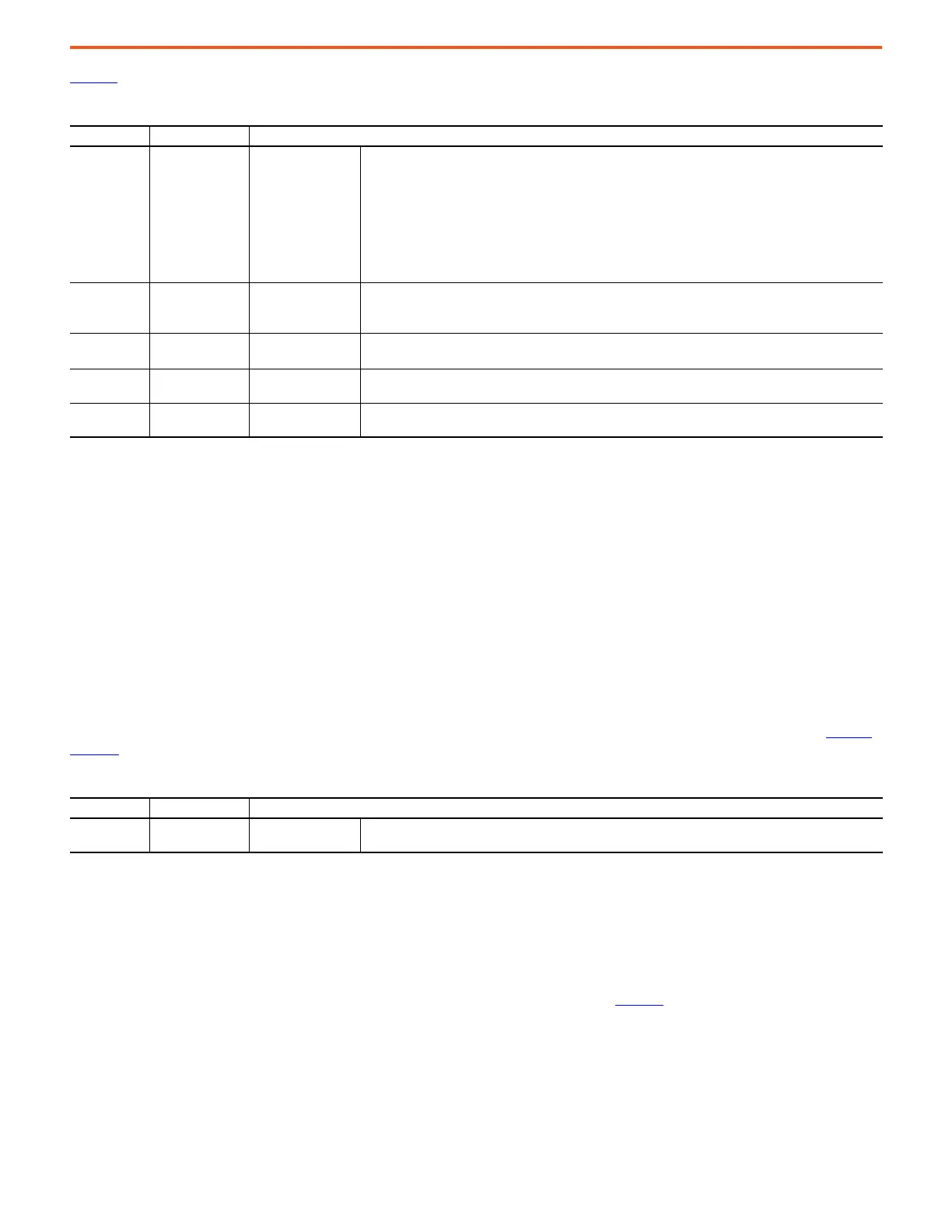
Table 27 - Current Control Loop Configuration and Parameter Settings
Parameter No. Parameter Name Description
13:74 [Cur Reg C/U Sel]
Cur Reg Calc/
User Select
Enter a value to select whether the current regulator uses calculated values or user-entered values for
proportional and integral gains.
Calculated values are determined by equations in the drive. These equations use value of parameters
13:75 [Cur Reg BW], 13:76 [Cur Reg Damping] and LCL parameters. Parameter values are as follows.
• Calculated (0) – selects the calculated 'c' values.
• User Entered (1) – selects the user-entered 'u' values.
• LoadCalcData (2) – copies the calculated 'c' values into the parameter for the user-entered 'u' values. This
is useful for starting with the calculated values and then adjusting them. After performing the copy, this
switch will revert to position User Entered (1).
13:75 [Cur Reg BW]
Current Regulator
Bandwidth
Enter a value to set bandwidth of the current regulator.
• This value is consumed by calculations that produce the calculated proportional and integral gains of the
regulator.
13:76 [Cur Reg Damping]
Current Regulator
Damping Factor
Enter a value to set damping of the current regulator.
• When 13:75 [Cur Reg BW] is set to 0.0, this value is ignored.
13:77 [u Cur Reg Kp]
Cur Reg Proportional
Gain - User Entered
Enter the value for the proportional gain of the current regulator that is used when 13:74 [Cur Reg C/U Sel] is
set to User Entered (1).
13:78 [c Cur Reg Kp]
Cur Reg Proportional
Gain - Calculated
Displays the value of the proportional gain of the current regulator that is used when 13:74 [Cur Reg C/U Sel]
is set to Calculated (0).
Table 28 - Active Damping Gain Parameter Settings
Parameter No. Parameter Name Description
13:81 [Actv Damping Gn] Active Damping Gain
Enter the value for the proportional gain in the algorithm for active damping of resonant frequencies in the
LCL filters.
 Loading...


