Rockwell Automation Publication 750-AT006D-EN-P - January 2022 53
Chapter 2 Product Features
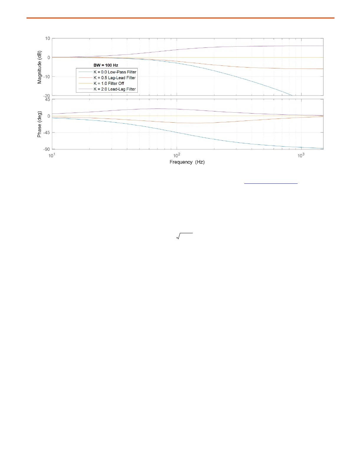
Figure 53 - First Order Lead-lag Filter Configurations
Lead-lag filters have four modes of operation depending on the gain K setting, similar to notch filters. The difference is that lead-lag filters
can only be configured as first order and notch filters can only be configured as second order. See Notch Filters
on page 46 for more
information.
• When K = 0, the lead-lag filter is configured to operate as a first order low-pass filter.
• When 0 < K < 1, the lead-lag filter is configured to operate as a first order lag-lead filter. It can be used to compensate for high
frequency gain boost associated with compliant load mechanics. With a known load ratio R and resonant frequency F
R
, a pole can be
placed at the anti-resonant frequency and a zero can be placed at the resonant frequency using the following calculations:
However, use of the filter in this way can make the drive more sensitive to disturbances. Furthermore, the load observer is
recommended to compensate for load compliance and disturbances because it typically does a better job without having to
determine these parameters.
• When K = 1, the lead-lag filter is off. This setting is the recommended and default mode of operation.
When K > 1, the lead-lag filter is configured to operate as a first order lead-lag filter. This setting is used to compensate for undesirable
dynamics caused by rate transitions between control loops.
Finite Impulse Response Filters
Finite Impulse Response (FIR) filters are digital filters where the output is a weighted sum of the recent inputs. They are inherently stable and
represented by the following equation.
where:
x (t) is the filter input signal
K
1
R 1+
--------------------=
 Loading...


