92 Rockwell Automation Publication 750-AT006D-EN-P - January 2022
Chapter 6 Active Front End Tuning
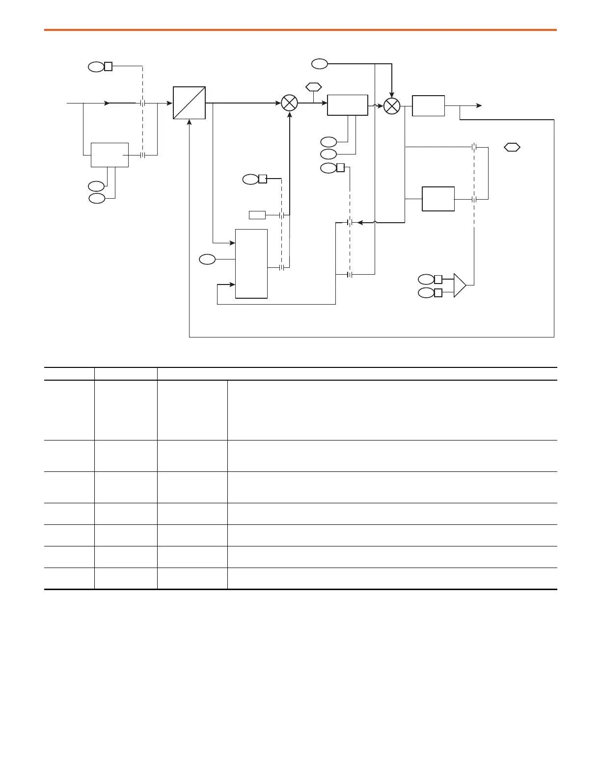
Figure 76 - Function Block Diagram of the PLL With DC Offset Parameters Shown
Loss of Synchronization Detection
The Loss of Synchronization detection capability helps to enhance the sensitivity and the reliability of the algorithm. The algorithm relies on
monitoring a transient error signal processed through a 1.6 ms filter and a steady-state error signal processed through a 160 ms filter. The
basic concept is to allow transient error with a higher amplitude for a very short period, as compared to a lower amplitude steady-state error
that is sustained a for a longer period. The steady-state error limit is set by 13:192 [BasicPLL Err Limit]. The corresponding transient error
limit can be calculated as follows:
PLL Transient Error= 3.5 x PLL Steady-state Error
Table 33 - Bus Observer Tuning Parameter Settings
Parameter No. Parameter Name Description
13:85 [PLL Config]
Phase Lock Loop
Configuration
Set and clear bits to configure the operation of the Phase Lock Loop (PLL). Bit values are as follows.
• Bit 1 PLL Unbl Rej enables rejection of AC line voltage unbalance in the PLL to synchronize the converter to
the line.
• Bit 2 PLL DC Ofst enables rejection of AC line voltage sensing offset.
• Bit 3 PLL Freq Src selects the PLL center frequency. When this bit is clear, the center frequency source is
the value in 13:30 [Nom Line Freq]. When this bit is set, the center frequency is generated internally.
13:86 [Basic PLL Kp]
Basic Phase Lock
Loop Proportional
Gain
Enter a value to set the Phase locked loop (PLL) proportional gain for the basic PLL with or without 2nd
harmonic elimination.
• Units are radians per Volt per second.
13:87 [Basic PLL Ki]
Basic Phase Lock
Loop Integral Gain
Enter a value to set the Phase locked loop (PLL) integral gain for the basic PLL with or without 2nd harmonic
elimination.
• Units are radians per Volt per second squared.
13:88 [Basic PLL Error]
Basic Phase Lock
Loop Error
Displays the Basic PLL error voltage.
13:89 [Unbl Rej Filt BW]
Unbalanced Rejection
Filter bandwidth
Enter a value to set the bandwidth of the Unbalanced Rejection filter.
13:90 [DC Offst Filt BW]
DC Offset Filter
Bandwidth
Enter a value to set the bandwidth of the DC Offset Rejection filter.
13:91 [DC Offst LPF BW]
DC Offset Low Pass
Filter Bandwidth
Enter a value to set the bandwidth of the DC Offset low pass filter.
88
+
+
+
–
3
85
2
0
1
90
91
3I
dq
85
1
0
1
0
1
0
1
85
3
307
0
307
1
30
89
87
86
0
OR
LPF
Integrator
Line Angle
AC Line Freq
Display Filter
Display Filter
Unbalance
Rejecon
2
nd
Harm Flt BW
PLL Unbl Rej
Basic PLL Kp
Basic PLL Ki
PLL Freq Src
PI Regulator
Basic PLL Error
Nom Line Freq
DC Offst Flt BW
DC Offst LPF BW
DC Offset
Cancellaon
Line Voltage
Metering [B1]
PLL DC Offst
 Loading...


