Rockwell Automation Publication 750-AT006D-EN-P - January 2022 21
Chapter 1 Background
has a squared relationship to it in units of [rad
2
/sec
2
]. In this drive however, K
PP
is in series with K
PI
and a factor of 2 is applied to each
gain.
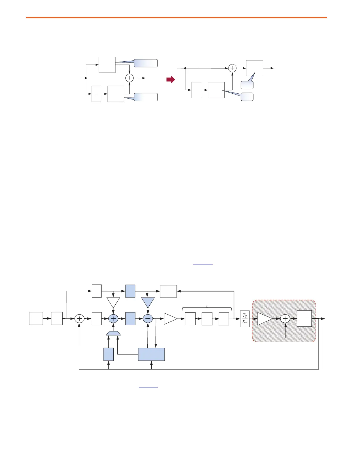
Figure 19 - Position Regulator – from Parallel to Series Form
As a result, all tuning parameters represent bandwidths of physically measurable signals that are easy to understand. More importantly,
removing the squared relationships simplifies math when tuning a drive, because all gains and filter bandwidths are now related to each
other by simple ratios. This approach makes the tuning experience more transparent and intuitive.
Use the following equation to convert legacy position loop gains to PowerFlex 755T gains.
Velocity Feed Forward Gain (K
VFF
) – During position-based moves, a theoretical command velocity profile is generated based on
acceleration rates, profile type, and jerk. The velocity feed forward gain scales this command velocity profile. The resultant velocity feed
forward signal is summed with the output of position loop to become the velocity command for the velocity regulator. The use of the velocity
feed forward gain provides a prediction of the motor velocity required to perform the move instead of waiting for the position error to
become large enough to produce an equivalent signal. Parameter 10:1760 [c Vel FF Gain] is applied as the velocity feed forward gain when
10:905 [System C/U Select] = Calculated. Parameter 10:1761 [u Vel FF Gain] is applied as the velocity feed forward gain when 10:905 [System
C/U Select] = User Entered. The default value is set to 100% in the drive, resulting in K
VFF
= 1.
Velocity Loop
The velocity loop is active in position and velocity control modes. In Position mode, the position, velocity, and torque loops are all enabled.
Here, the velocity loop consists of the highlighted elements that are shown in Figure 20.
Figure 20 - Velocity Loop
In Velocity mode, the velocity and torque loops are enabled and the position loop is replaced by a velocity reference command. Here, the
velocity loop consists of the highlighted elements in Figure 21
.
s
1
PP
K
PI
K
PP
S
K2
PowerFlex 755
PowerFlex 755T
PI
S
K2
s
1
K
PP
K
PP LegacyP839
2
---------------------------------------------------------- K
PI
K
PI LegacyP838
2
K
PP LegacyP839
----------------------------------------------------------------------------=,=
2
1
sJ
T
PI
s
PI
s
Fs
K
T
P
REG
V
REG
Velocity
Feedback
Filter
Position
Feedback
Velocity
Estimate
Feed
Forwards
Kvff Kaff
Position
Command
LP
LL
N
Torque Loop Filters
Load Torque
Load
Observer
K
J
Torque
Estimate
Adaptive
Tuning
RN
System Under Control
P
REF
 Loading...


