22 Rockwell Automation Publication 750-AT006D-EN-P - January 2022
Chapter 1 Background
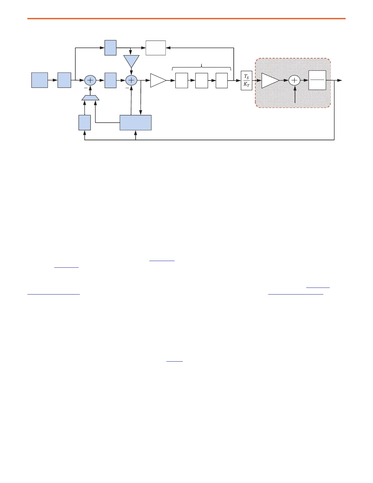
Figure 21 - Velocity Reference
Elements of the velocity loop are summarized:
Velocity Reference (V
REF
) – The velocity reference can come from various sources. Some are selected through digital inputs or via bit
manipulation of the Network Logic Command Word:
• HIM (local or remote)
•Analog Input
• Preset Speed Parameters
• Jog Speed Parameters
• Encoder Velocity Reference
•Network Communication
• Process PID Controller
• MOP - Motor Operated Potentiometer Function
See the PowerFlex 750 Reference Manual, publication 750-RM002
, and PowerFlex Drives with TotalFORCE Control Programming Manual,
publication 750-PM100
, for more information.
Reference Notch Filters (RN) – Two reference notch filters are placed on command signals to remove load-side resonances and vibration
that is common in robots, cranes, cantilevered loads, liquid sloshing, laser cutting, and material handling applications. See Load Side
Resonances on page 14 for more information. These filters are capable of adjustable width and depth. See Notch Filters on page 46 for more
information.
Velocity Feedback Filter (Fs) – The velocity feedback filter actually consists of two filters that work in combination to remove quantization
noise that is generated by low-resolution feedback devices. These filters are typically disabled when high-resolution feedback devices are
used. There is an FIR filter followed by a velocity feedback low pass filter on the primary feedback channel. There is another set of these
filters on the alternate feedback channel.
The primary feedback channel is used when the Automatic Tach Switchover feature is disabled or before a switchover has occurred.
Feedback is then switched from the primary to the alternate feedback channel when the Automatic Tach Switchover feature is enabled and
a switchover has occurred. Relevant parameters are given in Table 4
.
2
1
sJ
T
PI
s
Fs
K
T
V
REG
Velocity
Feedback
Filter
Position
Feedback
Velocity
Estimate
Feed
Forward
Kaff
LP
LL
N
Torque Loop Filters
Load Torque
Load
Observer
K
J
Torque
Estimate
Adaptive
Tuning
RN
System Under Control
V
REF
 Loading...


