28 Rockwell Automation Publication 750-AT006D-EN-P - January 2022
Chapter 2 Product Features
containing 1/K
T
in the drive. T
S
is the scaled torque in units of [percent motor rated torque with respect to revolutions], which equals motor
rated torque in [N•m] divided by (100*2)
Figure 25 - System with a Rigid Load
The motor and load mechanics are represented with J
T
, the total of all inertia in the system. In this case, the torque scaler K
J
= J
T
/T
S
brings
the system under control to unity gain. This places K
J
at its maximum value because J
T
is the largest inertia value the system can be. As a
gain in the signal path, K
J
generates a high system gain that produces great performance when the system is in fact rigid. However, if the
system is not rigid, and most systems are not, then this high gain could produce instability. As a result, the control loop and observer gains
must be reduced.
Also with high gain, the velocity loop and load observer only have enough stability margin to compensate for small disturbances in the load
torque. For rigid systems, the load ratio R > 0 is calculated by Autotune or it is a known positive nonzero value and J
T
= J
M
*(R+1).
Non-Rigid Load
Most mechanical systems have a non-rigid load. They exhibit some combination of compliance, backlash, unknown dynamics, and unknown
or changing inertia. Here, only the effect of motor inertia (J
M
) is immediate and a direct multiplier on rigid body mechanics. As a result, the
motor and load mechanics are represented with J
M
and the effect of load inertia is dynamic and reflected in the load torque signal being
applied to the motor shaft.
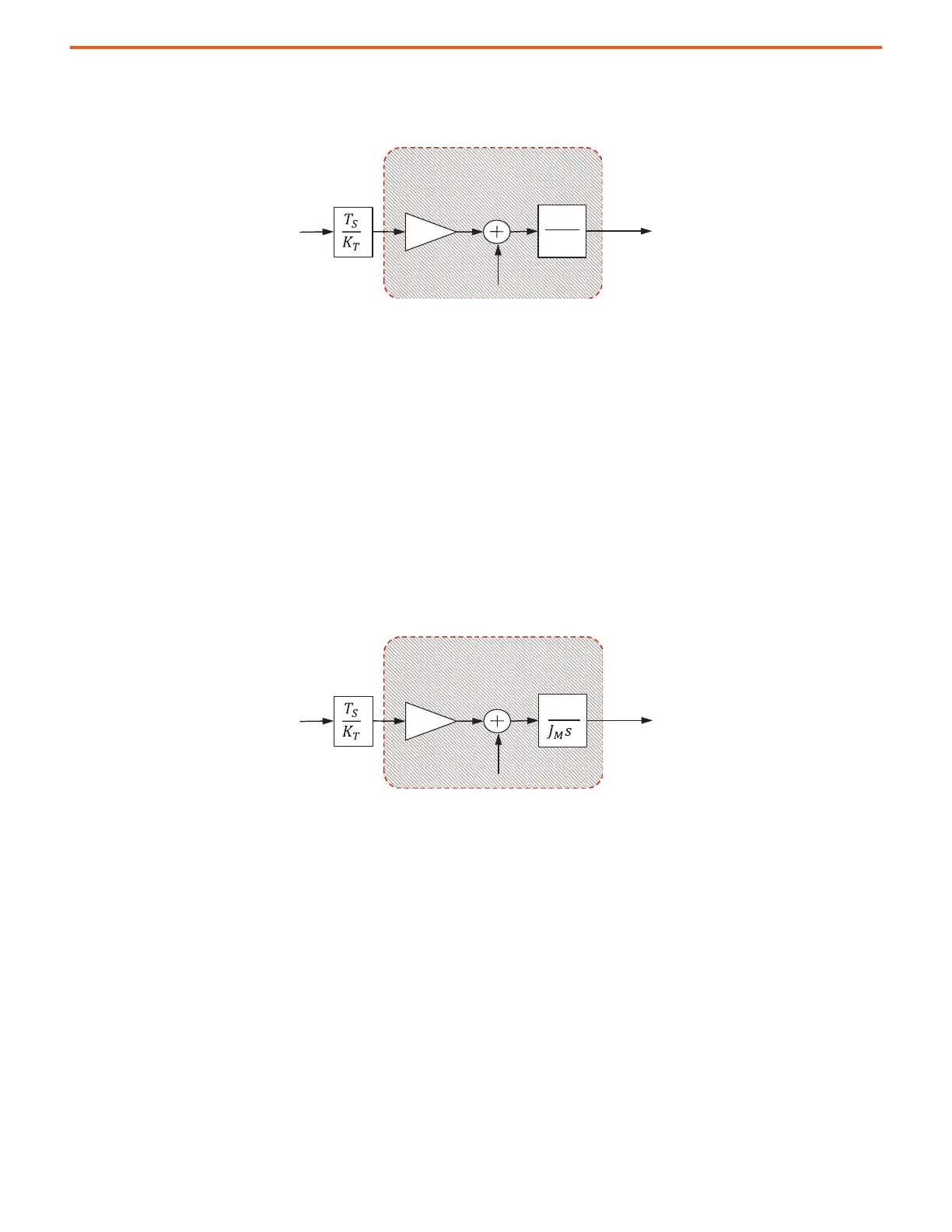
Figure 26 - System with an Unknown, Non-rigid, or Changing Load
In this case, the torque scaler K
J
= J
M
/T
S
brings the system under control to unity gain. This places K
J
at its minimum value because J
M
is the
smallest inertia value the system can be; a no-load condition. As a gain in the signal path, K
J
generates a lower system gain, which allows the
control loop and observer gains room to be increased. Here, the velocity loop and load observer have enough stability margin to compensate
for the entire load torque. For non-rigid systems or when the load is unknown, the load ratio R = 0.
Calculation for Both Rigid and Non-rigid Loads
It has been shown that K
J
= J
T
/T
S
for rigid loads and K
J
= J
M
/T
S
is for non-rigid loads. In the drive, torque scaler is calculated as
K
J
=J
M
*(R+1)/T
S
to allow for all cases.
2
1
sJ
T
K
T
Motor and
Load
Mechanics
Motor
Electrical
Load
Torque
System Under Control
Motor
Position
1
2
K
T
Motor and
Load
Mechanics
Motor
Electrical
Load
Torque
System Under Control
Motor
Position
 Loading...


