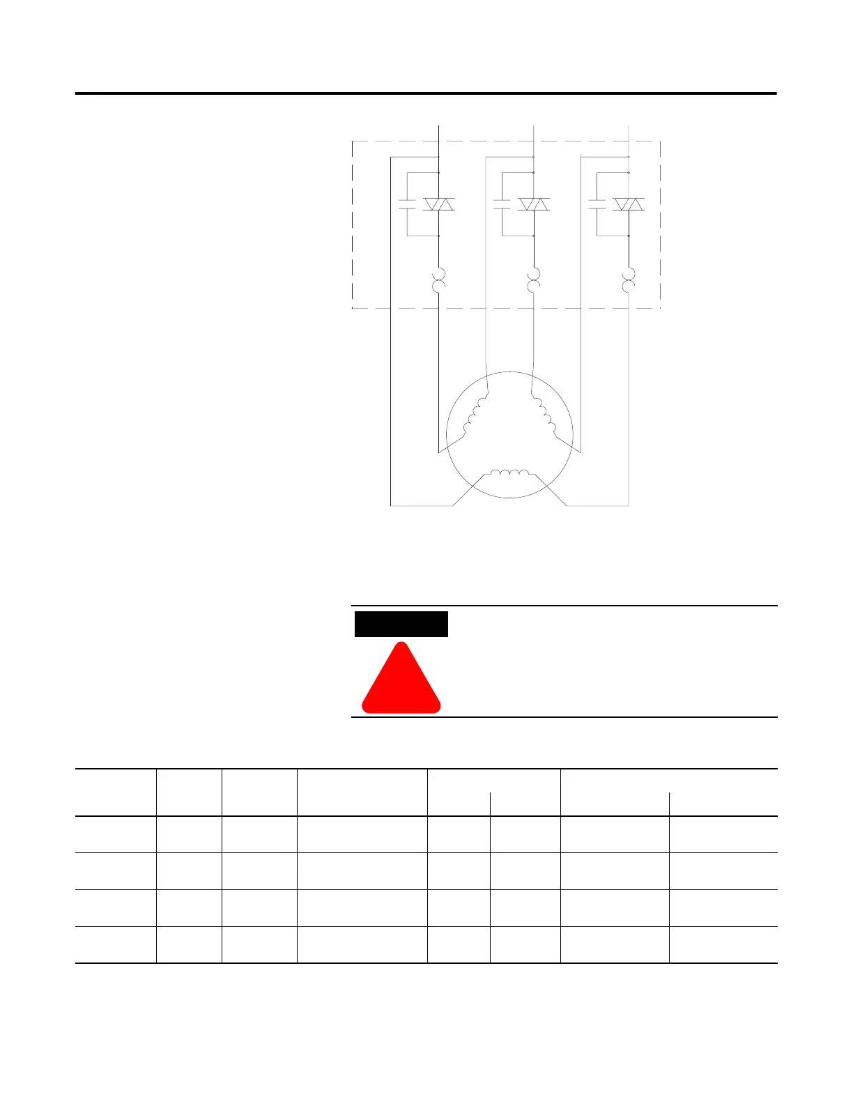
3-4 Wiring
Figure 3.4 Delta Power Wiring diagram
Power lugs are available as optional kits. Each kit contains three lugs.
The number of terminal lugs required is listed in the table below.
Table 3.A also provides the lug wire capacity and the tightening
torque requirements.
Table 3.A Lug Wire Capacity and Tightening Torque
1
L
L
2
T
4
T
T
12
T
T
1
T
ATTENTION
!
Terminal covers are available which can make the
product deadfront (IP2X) safe. See Appendix D for
the appropriate catalog numbers for ordering.
SMC
Rating
Lug Kit
Cat. No.
Wire Strip
Length
Conductor
Range
Max. No. Lugs/Pole Tightening Torque
Line Side Load Side Wire — Lug Lug — Busbar
5…85 A — 18…20 mm
2.5…85 mm
2
(#14…3/0 AWG)
— — 14.7 N•m
(130 lb.-in.)
—
108…135 A
(Series A)
199-LF1 18…20 mm
16…120 mm
2
(#6…250 MCM)
6 6 31 N•m
(275 lb.-in.)
23 N•m
(200 lb.-in.)
201…251 A 199-LF1 18…20 mm
16…120 mm
2
(#6…250 MCM)
6 6 31 N•m
(275 lb.-in.)
23 N•m
(200 lb.-in.)
317…480 A 199-LG1 18…25 mm
25…240 mm
2
(#4…500 MCM)
6 6 42 N•m
(375 lb.-in.)
45 N•m
(400 lb.-in.)

 Loading...


