PowerFlex 40 Standard Configured Drive Standard Features and Options 1-7
Publication 23B-IN001G
Input Power Wiring
Refer to the PowerFlex 40 User Manual for additional detailed information
about input power wiring recommendations and selection.
To connect AC input power to the drive package:
❏ 1. Select the proper wire size according to NEC and all applicable local
codes and standards. Note that you must punch openings in the Option
Cabinet of the desired conduit size, following NEC and all applicable
local codes and standards. Power terminal block specifications are listed
in Table 1.B
.
❏ 2. Connect the three-phase AC input power leads (three-wire VAC) to the
appropriate terminals. Connect the AC input power leads to terminals
L1, L2, L3 on the fused disconnect switch or motor circuit protector.
Note: Drive Input Fused Disconnect Switch (-P6) and Drive Motor
Circuit Protector (-P3) options are bottom fed. Drive Input Fused
Disconnect Switch (-P6T) and Drive Motor Circuit Protector (-P3T)
options are top fed.
❏ 3. Tighten the AC input terminal power terminals to the proper torque
according to drive type as shown in Table 1.B
.
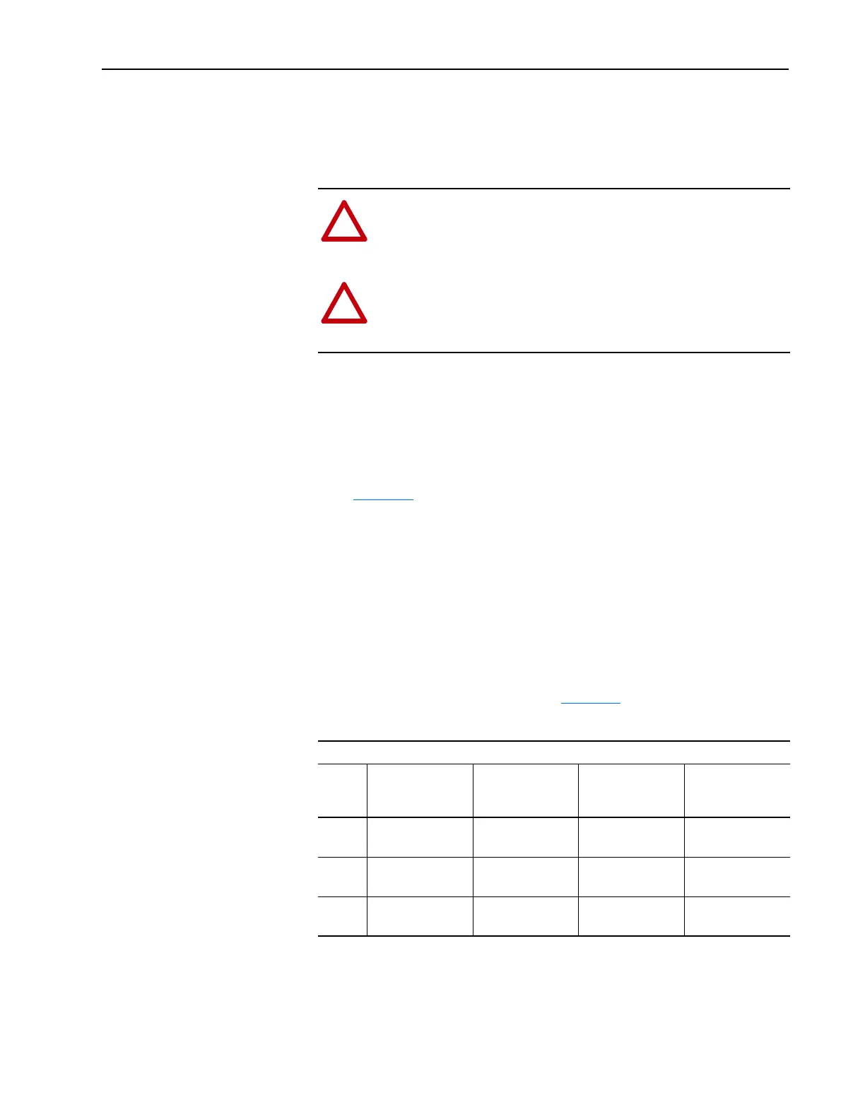
Table 1.B Component Current Ratings and Wire Sizing
!
ATTENTION: Protect the contents of the options cabinet from
metal chips and other debris while drilling the conduit openings.
Failure to observe this precaution could result in damage to, or
destruction of, the equipment.
!
ATTENTION: Do not route signal and control wiring with
power wiring in the same conduit. This can cause interference
with drive operation. Failure to observe this precaution could
result in damage to, or destruction of, the equipment.
PowerFlex 40 SPD Drive Rating - 480V
HP Continuous
Current Rating
Amps
Factory Power
Wire Size
(1)(2)
(1)
Wire is Black Hypalon.
(2)
Maximum/minimum sizes that the terminal block will accept - these are not recommendations.
Customer
Terminal Wire
Size
Operating Torque
0.5-3 30 2.5 mm
2
(14 AWG)
2.5-8.4 mm
2
(14-8 AWG)
4.0 N-m
(35 lb.-in.)
5-7.5 30 3.5 mm
2
(12 AWG)
2.5-8.4 mm
2
(14-8 AWG)
4.0 N-m
(35 lb.-in.)
10-15 60 4.0 mm
2
(10 AWG)
2.5-16.0 mm
2
(14-4 AWG)
4.0 N-m
(35 lb.-in.)

 Loading...