103 of 136
The State Diagram faceplate can be accessed by pressing the “State Diagram” button. While in Program mode, the state
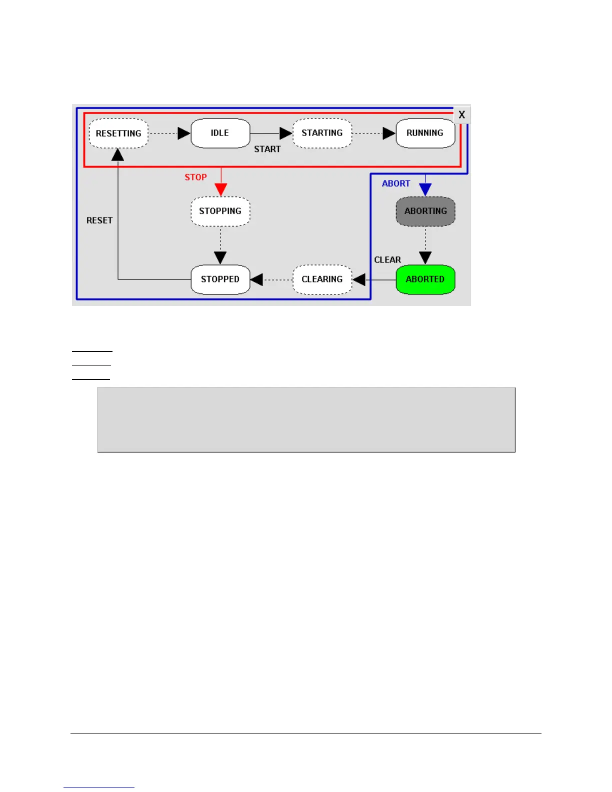
diagram illustrates the machine operational model:
The states with a dashed outline indicate a transitional state; while the solid line indicates an end state.
Depending on your current machine state, use the following commands to transition between states:
ABORTED – Press Clear Faults ABORTED CLEARING STOPPED
STOPPED – Press Start STOPPED RESETTING IDLE STARTNG RUNNING
RUNNING – Press Stop RUNNING STOPPING STOPPED
The machine is placed into the ABORTED state whenever a drive fault condition and/or a state transition
error has been detected. The machine is also placed into the ABORTED state on Power Up or during “first
scan” (i.e. Program to Run Mode) of the controller. Refer to the Alarm History faceplate to determine the
cause for the ABORTED condition.
If you opened the State Diagram faceplate, close it by pressing the [X] in the top-right corner.

 Loading...


