Installation/Wiring 1-13
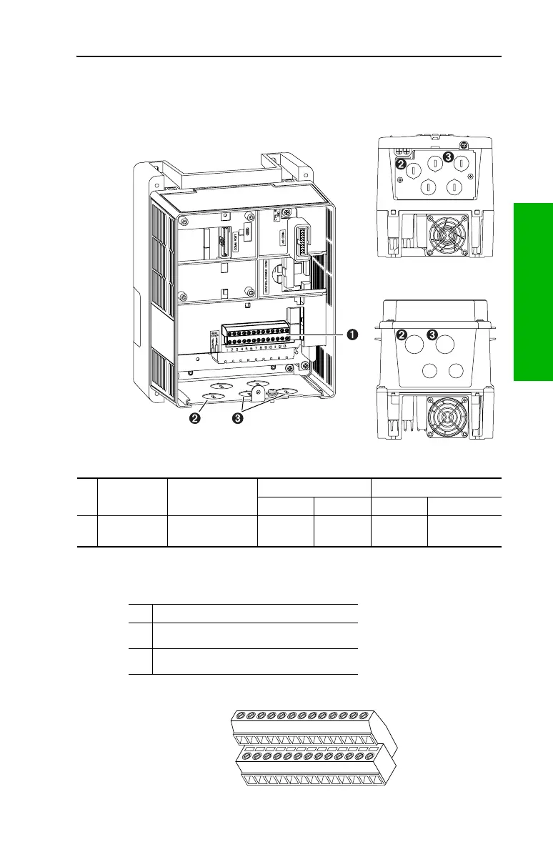
I/O Terminal Block
Figure 1.9 Typical I/O Terminal Block Location (B Frame Shown)
Table 1.F I/O Terminal Block Specifications
Table 1.G Wire Routing Recommendations
Figure 1.10 I/O Terminal Positions
No. Name Description
Wire Size Range
(1)
Torque
Maximum Minimum Maximum Recommended
➊
I/O Terminal
Block
Signal & control
connections
1.5 mm
2
(16 AWG)
0.05 mm
2
(30 AWG)
0.55 N-m
(4.9 lb.-in.)
0.5 N-m
(4.4 lb.-in.)
(1)
Maximum / minimum that the terminal block will accept - these are not recommendations.
No. Description
➋
Suggested entry for communication wiring.
➌
Suggested entry for I/O and control wiring.
14
26
13
1
 Loading...