Installation/Wiring 1-15
Hardware Enable Circuitry (Enhanced Control Only)
By default, the user can program a digital input as an Enable input. The
status of this input is interpreted by drive software. If the application
requires the drive to be disabled without software interpretation, a
hardware enable configuration can be utilized. This is done by removing
the enable jumper (ENBL JMP) and wiring the enable input to “Digital
In 6” (see below).
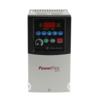
1.Remove drive cover as
described on pages 1-1 and 1-2.
2.Locate and remove the Enable
Jumper on the Main Control
Board (see diagram).
3.Wire Enable to “Digital In 6”
(see Table 1.H
).
4.Verify that 366 [Digital In6
Sel] is set to option 1 “Enable”.
Safe Off Board (Enhanced Control Only)
The PowerFlex Safe-Off board, when
used with suitable safety components,
provides protection according to EN
954-1:1997; Category 3 for safe off and
protection against restart. The PowerFlex
safe off option is just one safety control
system. All components in the system
must be chosen and applied correctly, to
achieve the desired level of operator
safeguarding.
Table 1.I Terminal Description
For detailed information on installing and wiring a safety relay system,
refer to the DriveGuard Safe-Off Option for PowerFlex AC Drives
User Manual, publication PFLEX-UM001….
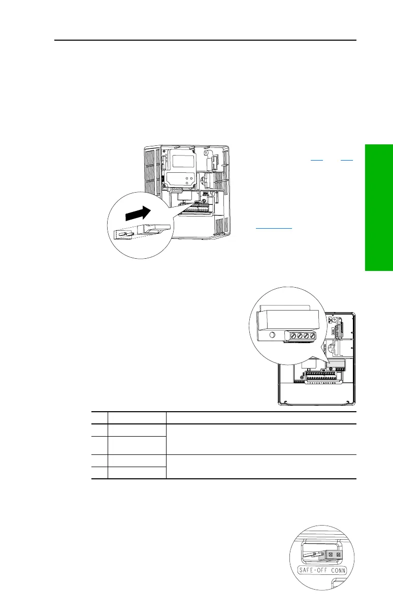
Important: If the Safe-Off board is removed from
the drive, pins 3 and 4 of the Safe-Off
Connector must be jumpered for the
drive to run. If the Safe-Off board or
the jumper is not installed, and the
drive is commanded to run, an F111
“Enable Hardware” fault will occur.
No. Signal Description
1 Monitor - N.C. Normally closed contacts for monitoring relay status.
Maximum Resistive Load: 250V AC / 30V DC / 50 VA / 60 Watts
Maximum Inductive Load: 250V AC / 30V DC / 25 VA / 30 Watts
2 Common - N.C.
3 +24V DC
Connections for user supplied power to energize coil.
4 24V Common
1234
 Loading...