EN
65
6 Description of connections
To access the control unit. remove the barrier head.
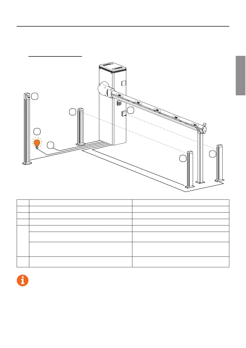
Figure 1-2-3 shows connection diagrams.
6.1 Typical installation
2
2
3
3
4
1
5
Recommended cable
1 Power supply H07RN-F 3x1,5 mm
2
double insulated cable
2 Photocell - Receiver F4ES/F4S Cable 5x0,5 mm
2
(max 20 m)
3 Photocell - Transmitter F4ES/F4S Cable 3x0,5 mm
2
(max 20 m)
4
Key selector R85/60 Cable 3x0,5 mm
2
(max 20 m)
Keypad H85/TTD - H85/TDS
(connecting to H85/DEC - H85/DEC2)
Cable 2x0,5 mm
2
(max 30 m)
H85/DEC - H85/DEC2
(connecting to control unit)
Cable 4x0,5 mm
2
(max 20 m)
The number of conductors increases when using more
than one output contact on H85/DEC - H85/DEC2
5
Barrier open indicator
Power supply 24V DC 3W max
Cable 2x0,5 mm
2
(max 10 m)
SUGGESTIONS: with existing installations, we recommend checking the cross section of the cables and that
the cables themselves are in good condition.