EN
69
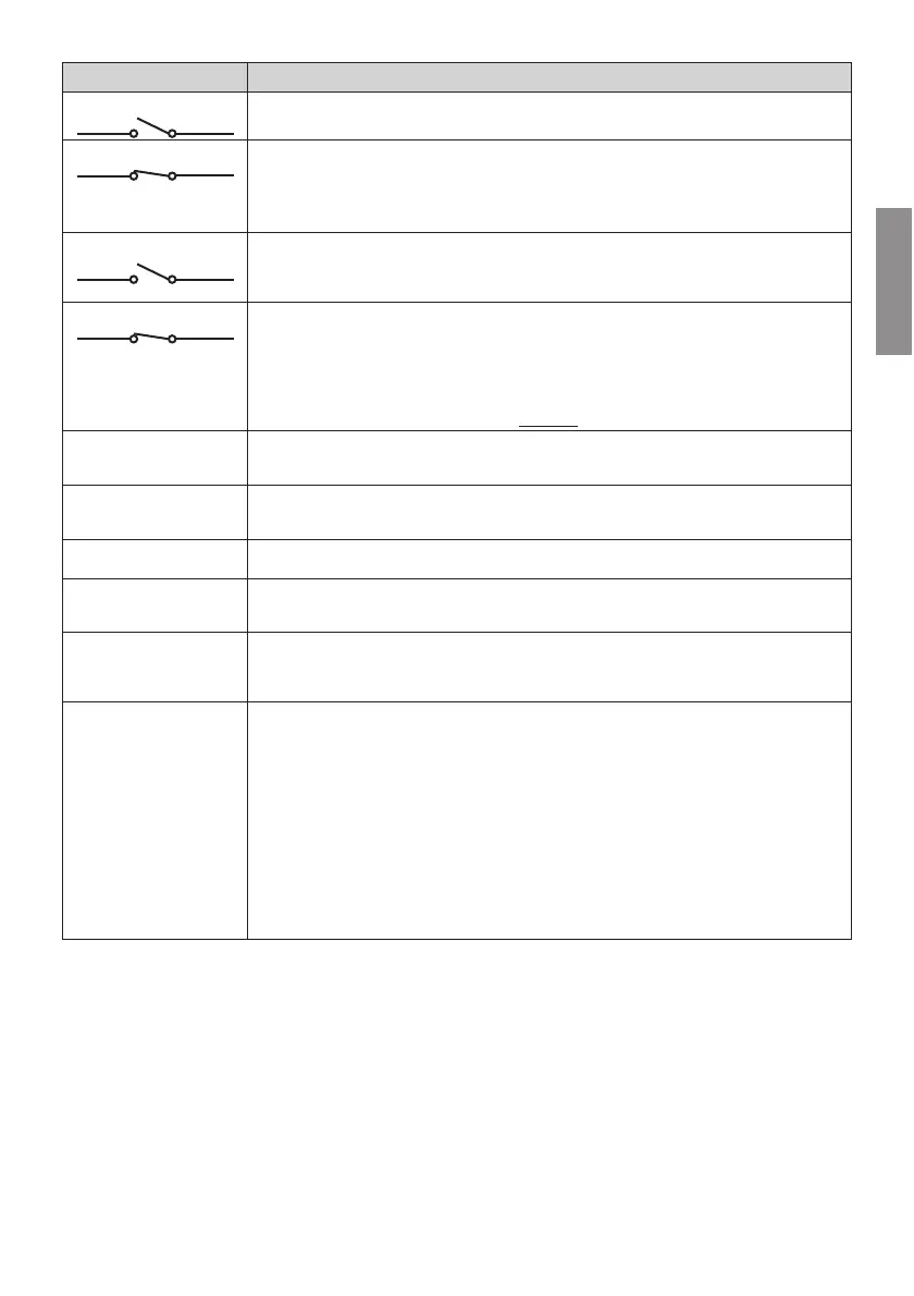
CONTACT DESCRIPTION
32(AP) 28(COM)
Open command input (NO).
32(AP) 28(COM)
The command input (N.C.) available for the connection of the sensor of the ACS/BA/60 detachable
FEVVMIVFSSQGSYTPMRKW]WXIQƼK
When the ACS/BA/60 detachable boom safety system intervenes, the contact switches from N.C.
to N.O.
Enable the contact via parameter .
33(ORO) 34(COM)
Clock timer contact input (N.O.).
When the clock function is active, the barrier opens and remains open.
At the end of the programmed time set with the external device (clock) the barrier closes.
The function of this command is determined by parameter .
33(ORO) 34(COM)
The command input (N.C.) available for the connection of the sensor of the ACS/BA/60 detachable
FEVVMIVFSSQGSYTPMRKW]WXIQƼK
When the ACS/BA/60 detachable boom safety system intervenes, the contact switches from N.C.
to N.O.
Enable the contact via parameter .
For systems composed of two MASTER and SLAVE opposing barriers, connect the detachable boom
coupling system sensor of the SLAVE barrier STRICTLY to the ORO input of the SLAVE control unit.
ENC1
[E]GSRRIGXSVJSVGSRRIGXMRKXSIRGSHIVMRWXEPPIHSRQSXSVWIIƼK
WARNING! Always disconnect from electrical power before disconnecting or connecting the encoder
cable.
ENC2
[E]GSRRIGXSVJSVGSRRIGXMRKXSIRGSHIVMRWXEPPIHSRSRIWMHISJQSXSVWIIƼK
WARNING! Always disconnect from electrical power before disconnecting or connecting the encoder
cable.
LED LIGHT
Connector for the (OPTIONAL) B73/EXPWMKREPHIZMGIGSRRIGXMSRERHƽEWLMRKPMKLXWMRWXEPPIHSRXLI
XSTGSZIVWIIƼK
LOCKS
Connectors for connecting lock device microswitch and safety stop microswitch on barrier inspection
LEXGLGSRRIGXMSRRSXWYTTPMIHF]63+)68)',2303+=WIIƼK
Jumper the other connector if only one connector is connected.
RECEIVER CARD
Connector for slot-in radio receiver board.
8LIGSRXVSPPIVLEWX[SVEHMSVIQSXIGSRXVSPJYRGXMSRWF]HIJEYPX
! 46WXITQSHIGSQQERHQSHMƼEFPI[MXLTEVEQIXIV
! 46GPSWIGSQQERHQSHMƼEFPI[MXLTEVEQIXIV
B71/BCHP
BI/BCHP
BATTERY CHARGER
BI/BAT/KIT
BATTERY KIT
2x12 Vdc 4.5 Ah
(AGM type ONLY)
Connector for slot-in battery charger board.
In the event of a mains power loss, the controller unit is powered by the batteries. When battery power
is used, the message E$WWMWWLS[RSRXLIHMWTPE]ERHXLIƽEWLMRKPMKLXƽEWLIWFVMIƽ]EXMRXIVZEPW
until mains power is restored or until the battery voltage drops below the minimum permissible limit.
In this case, EW/2 (Battery Low) is shown on the display and the controller unit accepts no commands.
If mains power is lost while the boom is moving, the boom stops and then automatically resumes the
interrupted manoeuvre after 2 seconds.
By setting parameter to a value different than , the battery management is enabled. With
parameter the battery operation limitation type is enabled when the voltage drops under a certain
threshold.
Parameter is not available for SLAVE automation systems.
WARNING! the batteries must always be connected to the electronic controller unit in order to charge.
Periodically (at least every 6 months), check that the batteries are in good working order.
For more information, refer to the installation manual for the B71/BCHP or BI/BCHP battery charger.