10. Once the previous step is completed reader automatically ends the Memory Reset and
switches to normal operation.
Note: If in the step 6 no function is selected within 9 s or both steps are skipped with # key then
Memory Reset is completed with default settings i.e. IN1=[29] and IN2=[28]. It is forbidden to
assign the same functions to both inputs except for the function [11].
Memory Reset procedure(variant 3 for RACS and RS232 formats):
1. Power down the unit (or place jumper on RST contacts).
2. Remove all connections from CLK, IN1 and RTS lines.
3. Make electrical bridge between CLK and IN1.
4. Restore power (or remove jumper from RST contacts).
5. While LED OPEN (green) is flashing and is accompanied with continuous sound
disconnect CLK from IN1.
6. Wait till LED SYSTEM starts flashing.
7. Enter three digits which will configure the reader for required operating mode i.e.
[000].. [003], [01x] or [040]. Reader generates two beeps with every entered digit.
8. Once the previous step is completed reader automatically ends the Memory Reset and
switches to normal operation.
Note: When in step 7 an unknown operating mode is entered or no operating mode is entered for
20 s then reader will automatically exit the Memory Reset procedure.
7. O P E R A T I N G M O D E S
The factory new reader is pre-configured with [030]: Offline mode, Simple Standalone. In
order to change operating mode reader should be connected to PC (RARC software) or
reprogrammed manually (Memory Reset).
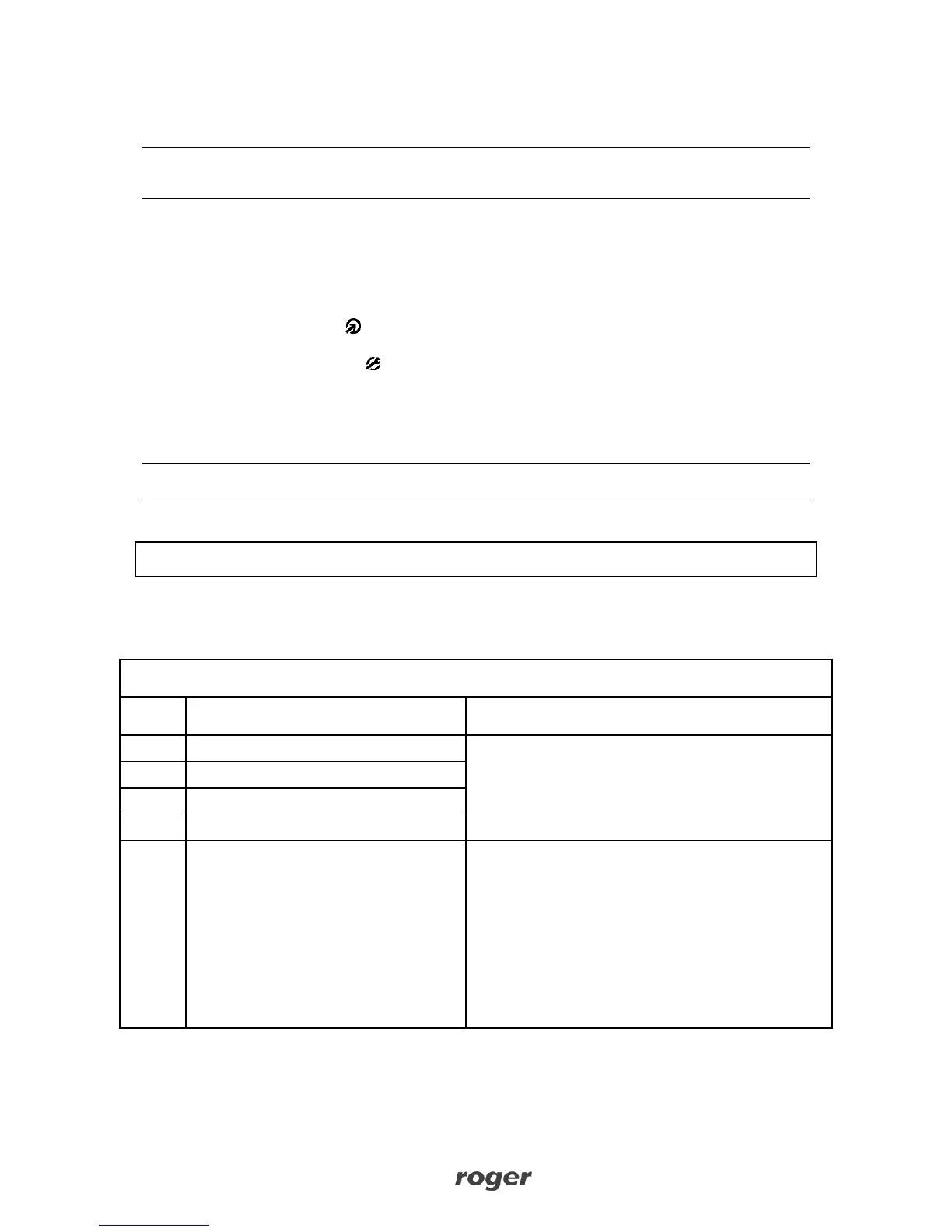
Reader is connected to the host through RS232
(9600,N,8,1) serial interface. Each key pressed is
transmitted separately as HEX BCD digit. Key coding
as below:
Card output format:
STX (02h) / Data (10 x hex digits coded ASCII) / CR
(0Dh) / LF (0Ah) /ETX (03h)
Key output format:
STX (02h) / Data (2 x hex digits coded ASCII) / CR
(0Dh) / LF (0Ah) / ETX (03h)