When lost or stolen a new MASTER and INSTALLER cards (PIN-s) can be reprogrammed in
the reader.
When the reader has been set for Terminal Mode (online unit connected to the host
controller), programming of MASTER and INSTALLER users can be skipped.
A new factory delivered unit is configured with [030] Offline mode, Simple Standalone.
The reader should be mounted near the supervised door on a vertical piece of supporting
structure.
Disconnect power supply before making any electrical connections.
Be aware that the installation of reader directly on the metal type surface will reduce card
reading distance.
For installations on a metal surface you can place a non-metallic 10 mm thick spacer (a
plastic/plaster plate etc.) between the reader and the supporting structure.
For installations with two readers to be mounted on the opposite sides of the same wall and
aligned along the same geometrical axis, place a metal plate between them and make sure
none of two readers has direct contact with it (allow min. 10 mm space). Be aware that the
reading distance will be reduced.
For best results mount the proximity readers at least 0.5 m apart.
When using separate power supply sources, short all power supply negatives (ground).
It is recommended to ground the negative power supply line (only at one point).
With its relatively weak electromagnetic field generation, reader should not cause any
harmful interference to operation of other equipment. However, its card reading
performance can be affected by other interference generating devices, especially radio
waves emitting equipment or CRT computer monitors.
If card reading performance of the reader deteriorates (e.g. reduced reading range or
incorrect readings) consider relocation.
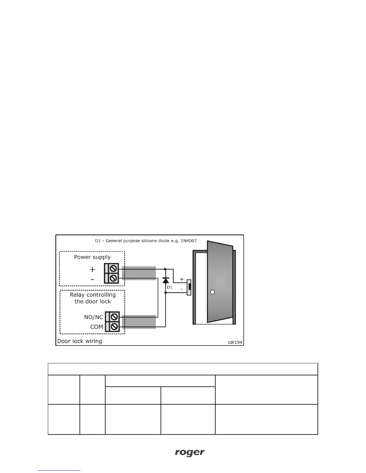
In standalone mode, always connect a general purpose diode (e.g. 1N4007) in parallel to a
door lock and place the diode as close as possible to the lock.