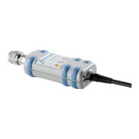
R&S NRP-Z11/21/31/41/61/211/221 Unpacking the power sensor
1137.7470.12 1.1 E-8
1 Putting into Operation
Follow the instructions below precisely to prevent damage to the power sensor –
particularly when you are putting it into operation for the first time.
Unpacking the power sensor
Remove the power sensor from its packing and check that nothing is missing. Inspect all items for
damage. If you discover any damage, inform the carrier responsible immediately and keep the packing
to support any claims for compensation.
It is also best to use the original packing if the power sensor is to be shipped or transported at a later
date.
The power sensor contains components which can be destroyed by electrostatic
discharges. To prevent this from happening, never touch the inner conductor of the RF
connector and never open the power sensor.
Connecting the power sensor
To prevent EMI, the sensor must never be operated with its enclosure wholly or partially
removed. Only use shielded cables that meet the relevant EMC standards.
Never exceed the maximum RF power limit. Even brief overloads can destroy the sensor.
The R&S NRP-Z41 and R&S NRP-Z61 power sensors have a new type of ball-bearing RF
connector. Since the friction with this design is considerably less than with conventional
RF connectors, a reproducible connection is ensured even at relatively low torques. Make
sure that the sensor body can still be turned opposite the mating part. Do not try to
prevent this by increasing the torque above the permissible value or by tightening the
connection by turning the sensor body.
Caused by their different frequency ranges, the R&S NRP-Z11/21/31/41/61/211/221 power sensors
have different RF connectors. In this context, the following sections will refer to Table 1-1:

 Loading...