PC control R&S NRP-Z91
1168.8579.12 1.4 E-6
Connecting the sensor to the DUT
The power sensor R&S NRP-Z91 has a male N connector and so can be connected to any standard
female N connector. Using light pressure, and keeping the male N connector perpendicular, insert it into
the female N connector and tighten the N connector locking nut (right-hand thread).
Operation via the Active USB Adapter R&S NRP-Z3
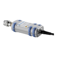
Fig. 1-3 shows the configuration with the Active USB Adapter R&S NRP-Z3, which also makes it
possible to feed in a trigger signal for the Timeslot and Trace modes. The order in which the cables are
connected is not critical.
Fig. 1-3 Configuration with Active USB Adapter R&S NRP-Z3
The plug-in power supply for the R&S NRP-Z3 can be powered from a single-phase AC source with a
nominal voltage range of 100 V to 240 V and a nominal frequency between 50 Hz and 60 Hz. The plug-
in power supply autosets to the applied AC voltage. No manual voltage selection is required.
The plug-in power supply comes with four primary adapters for Europe, the UK, the USA and Australia.
No tools of any kind are required to change the primary adapter. The adapter is pulled out manually and
another adapter inserted until it locks (Fig. 1-4).
Fig. 1-4 Changing the primary adapter
 Loading...


