6
List of Added Tone-FX
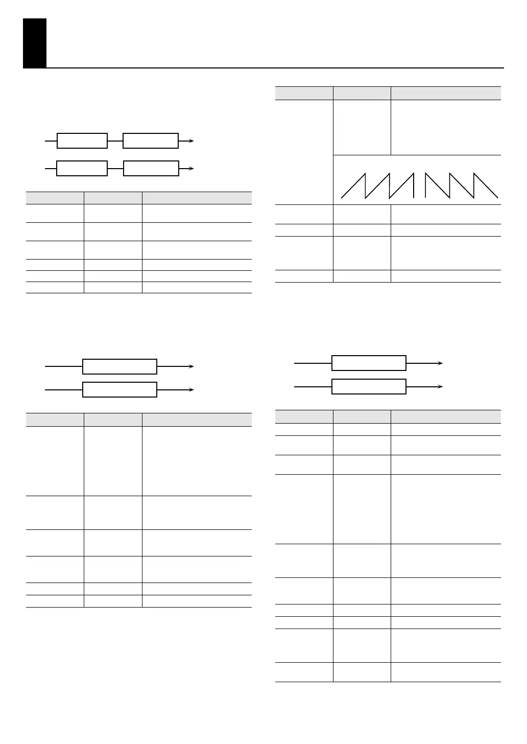
42: Low Boost
Boosts the volume of the lower range, creating powerful
lows.
fig.MFX-04
43: Super Filter
This is a filter with an extremely sharp slope. The cutoff
frequency can be varied cyclically.
fig.MFX-05
44: Step Filter
This is a filter whose cutoff frequency can be modulated in
steps. You can specify the pattern by which the cutoff
frequency will change.
fig.MFX-06
Parameter
Value Description
Boost
Frequency #1
50–125 Hz
Center frequency at which the lower
range will be boosted
Boost Gain #2 0– +12 dB
Amount by which the lower range will
be boosted
Boost Width
WIDE, MID,
NARROW
Width of the lower range that will be
boosted
Low Gain -15– +15 dB Gain of the low frequency range
High Gain -15– +15 dB Gain of the high frequency range
Level 0–127 Output level
Parameter
Value Description
Filter Type
LPF, BPF, HPF,
NOTCH
Filter type
Frequency range that will pass
through each filter
LPF
: frequencies below the cutoff
BPF:
frequencies in the region of the
cutoff
HPF:
frequencies above the cutoff
NOTCH:
frequencies other than the
region of the cutoff
Filter Slope -12, -24, -36 dB
Amount of attenuation per octave
-36 dB:
extremely steep
-24 dB:
steep
-12 dB:
gentle
Filter
Cutoff #1
0–127
Cutoff frequency of the filter
Increasing this value will raise the
cutoff frequency.
Filter
Resonance #2
0–127
Filter resonance level
Increasing this value will emphasize
the region near the cutoff frequency.
Filter Gain 0– +12 dB Amount of boost for the filter output
Modulation Sw OFF,ON On/off switch for cyclic change
L in
R in
L out
R out
Low Boost
2-Band EQ
2-Band EQ
Low Boost
L in
R in
L out
R out
Super Filter
Super Filter
Modulation Wave
TRI, SQR, SIN,
SAW1, SAW2
How the cutoff frequency will be
modulated
TRI:
triangle wave
SQR:
square wave
SIN:
sine wave
SAW1:
sawtooth wave (upward)
SAW2:
sawtooth wave (downward)
Rate #3
0.05–10.00 Hz,
note
Rate of modulation
Depth 0–127 Depth of modulation
Attack 0–127
Speed at which the cutoff frequency
will change
This is effective if Modulation Wave is
SQR, SAW1, or SAW2.
Level 0–127 Output level
Parameter
Value Description
Step 01–16
0–127 Cutoff frequency at each step
Rate #1
0.05–10.00 Hz,
note
Rate of modulation
Attack 0–127
Speed at which the cutoff frequency
changes between steps
Filter Type
LPF, BPF, HPF,
NOTCH
Filter type
Frequency range that will pass
through each filter
LPF:
frequencies below the cutoff
BPF:
frequencies in the region of the
cutoff
HPF:
frequencies above the cutoff
NOTCH:
frequencies other than the
region of the cutoff
Filter Slope -12, -24, -36 dB
Amount of attenuation per octave
-12 dB:
gentle
-24 dB:
steep
-36 dB:
extremely steep
Filter
Resonance #2
0–127
Filter resonance level
Increasing this value will emphasize
the region near the cutoff frequency.
Filter Gain 0– +12 dB Amount of boost for the filter output
Level 0–127 Output level
Input Sync Sw OFF, ON
Specifies whether an input note will
cause the sequence to resume from
the first step of the sequence (ON) or
not (OFF)
Input Sync
Threshold
0–127
Volume at which an input note will be
detected
Parameter Value Description
SAW1 SAW2
L in
R in
L out
R out
Step Filter
Step Filter
V-Synth_GT_v2_e1.book 6 ページ 2008年12月17日 水曜日 午前9時5分
 Loading...