24
V-SYNTH
a confirmation tone will be output.
• If both rotations are “OK,” you will automatically proceed to the next
test item.
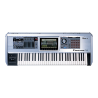
8: A/D Test1 (Bender & Modulation)
fig.13-12_70
Check the operation of bender and modulation.
* Make sure that the bender is not tilted when you enter this screen. (The A/D
value at the time you enter this screen is read as the electrical center.)
• Move the bender lever all the way to left and right.
• If movement to the far left produces a value of -128, movement to the far
right produces +127, and return to the center produces 0, the display will
indicate “OK” and a confirmation tone will be output.
• Move the bender lever all the way in the modulation direction.
• If movement to the modulation direction produces a value of 127 and
return produces a value of 0, the display will indicate “OK” and a
confirmation tone will be output.
• If “OK” is displayed for all tests, you will automatically proceed to the
next test item.
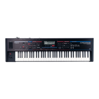
9: A/D Test2 (Volume x 23, Slider x 4)
fig.13-13_70
Check the rotary knobs and the sliders.
• Check each knob in order from the upper left.
• If a knob has no center detent, turn it “left-right-left.” Indications of
“OK” will be displayed if far left produces a value of 0, far right
produces a value of 127, and all the way back to the far left produces a
value of 0.
• If a knob has a center detent, turn it “left-right-center.” Indications of
“OK” will be displayed if far left produces a value of 0, far right
produces a value of 127, and center (detent) produces a value of 64.
• Check each slider in order from the left. Move each slider in the order of
“down-up-down.” Indications of “OK” will be displayed if the top
position produces a value of 127 and the bottom position produces a
value of 0.
• If the order is incorrect, the “OK” indication will not be displayed. A
sweep tone will be output during this operation.
• If the “OK” indication appears for all, you will automatically proceed to
the next test item.
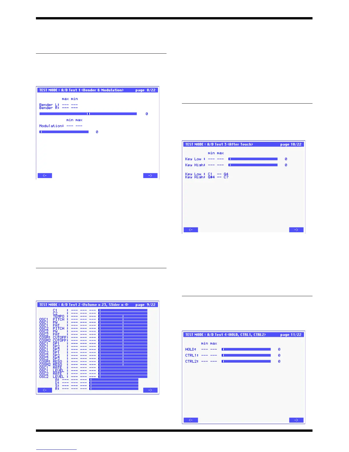
10 A/D Test3 (After Touch)
fig.13-14_70
Check aftertouch operation for the two regions of the keyboard.
L : Low region C2-G4 (SK-961 PWB LOW ASSY)
H : High region G#4-C7 (SK-961 PWB HI-AFT ASSY)
• In each keyboard region, firmly press down on any key, and then release
it.
• Indications of “OK” will be displayed if the maximum value is 127 and
the minimum value is 0, and a confirmation tone will be output.
• If “OK” is displayed for each test, you will automatically proceed to the
next test item.
f
11: A/D Test4 (HOLD, CTL1, CTL2)
ig.13-15_70
Problem
Items to check
“OK” is not displayed PANEL-R BOARD EN1
SUB BOARD IC2
Problem Items to check
“OK” is not displayed BENDER UNIT
SUB BOARD CN5, IC2
Problem
Items to check
TEMPO,C1,C2 NG PANEL-R,L BOARD, each VR, IC1,
IC2, IC3, IC4, CN1
SUB BOARD CN10, IC2, IC11
Problem Items to check
No response at all SUB BOARD IC5
Only the low region is NG Keyboard unit, SUB BOARD CN3,
Only the high region is NG Keyboard unit, SUB BOARD CN4,

 Loading...