64
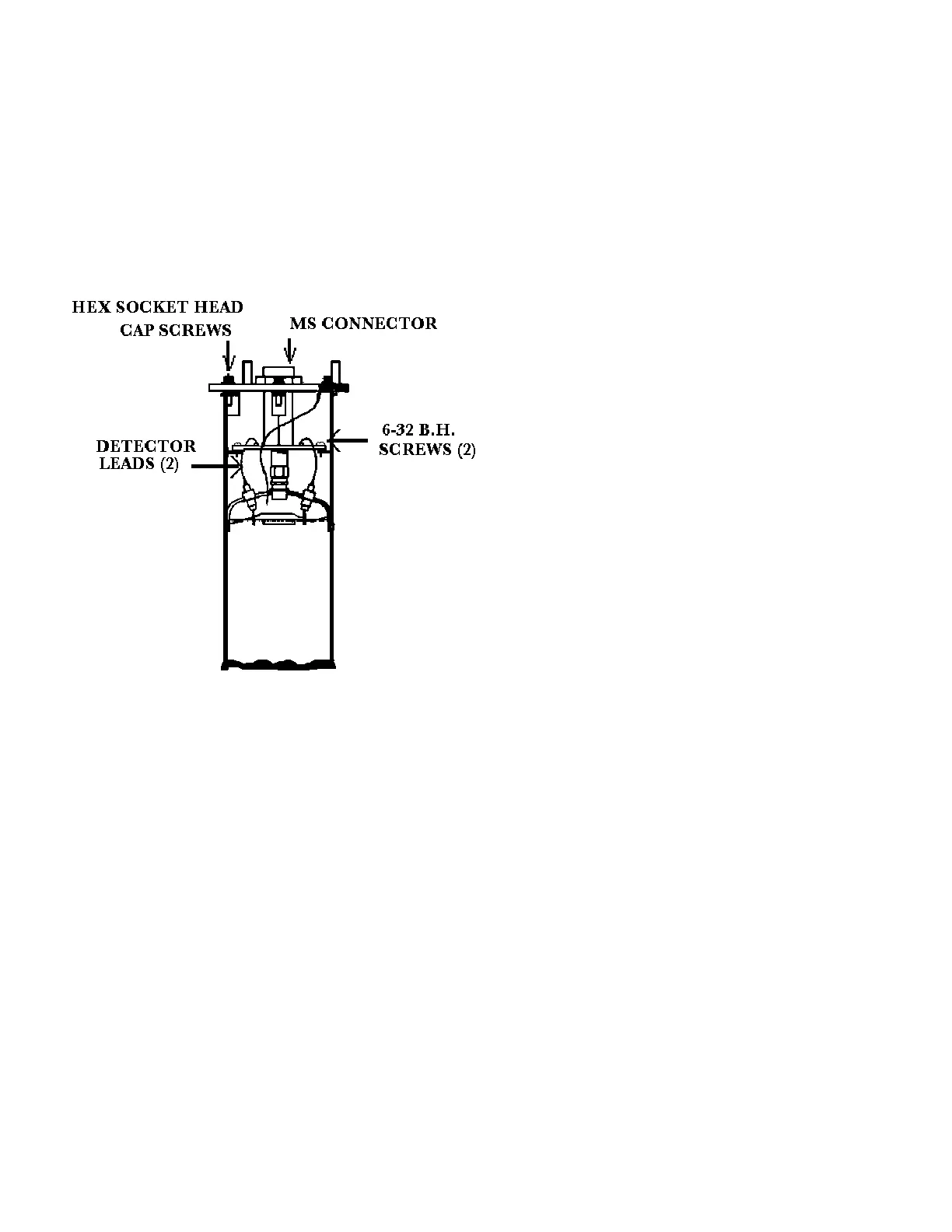
Removing the Detector
Amplifier Circuit Board
Replacing the Detector Circuit Board/Connector Assembly
Follow this procedure. CAUTION: Excessive twisting or bending can damage the detector leads.
1. Carefully straighten the detector leads to clear the holes in the new circuit board.
2. Place the new circuit board/connector assembly in the detector housing.
3. Using the two 6-32 binding head screws with a light coating of Gyptal, secure the board to the
detector housing.
4. Taking care the detector leads do not touch the printed circuit board, solder the detector leads to
the standoffs.
5. Replace the MS connector into the amplifier cover.
6. Ensure the flat gasket in the amplifier cover is in place and undamaged.
7. Using a light coating of Gyptal on the hex socket head screws, replace the amplifier cover.
Follow this procedure to remove the electrometer amplifier circuit
board:
1. Remove the amplifier cover by unscrewing the hex
socket head cap screws.
2. Remove the MS
connector from the
amplifier cover.
3. Remove the two 6-32
binding head screws,
which secure the
amplifier board to the
detector.
4. Using a low power
(60W) iron unsolder the
detector leads to the
printed circuit board
standoffs.
CAUTION: Excessive
twisting or bending can
damage the detector leads.