Installation
Page 10 RES-403 Version 1
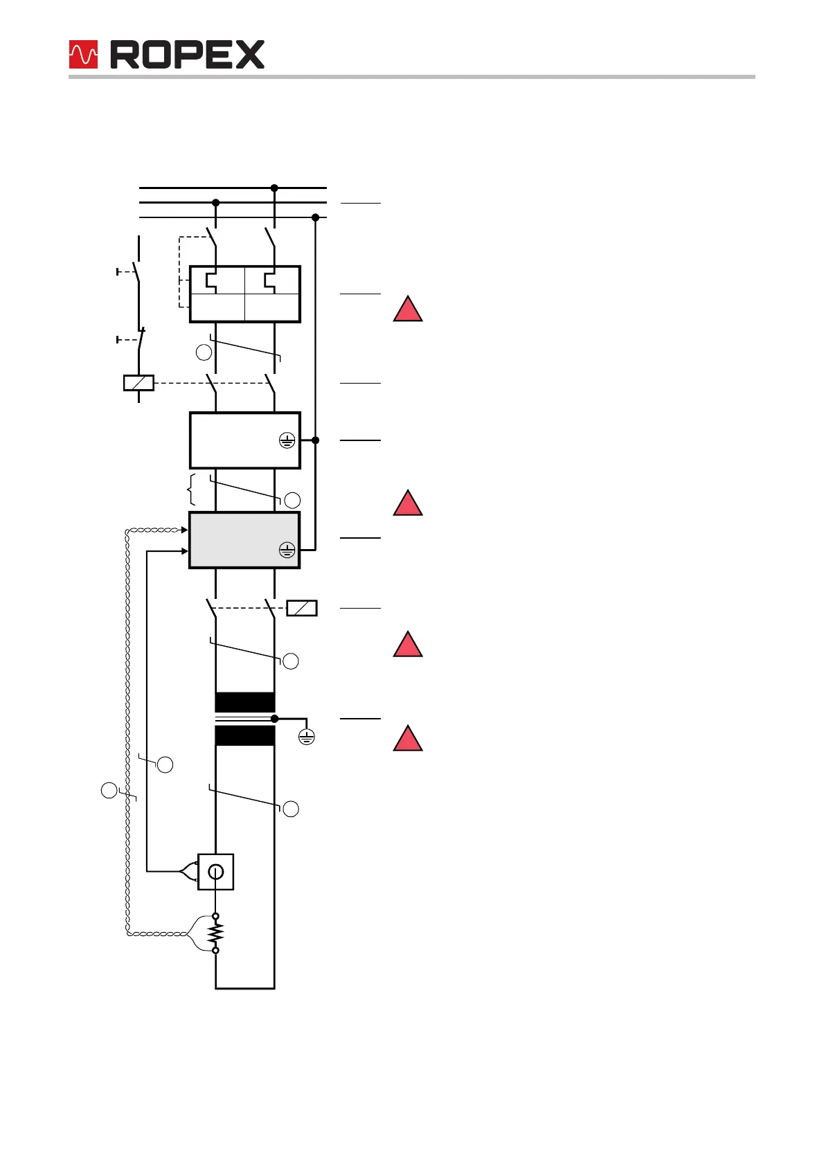
5.3 Power supply
temperature
controller
U
R
I
R
R
PRIM.
U
1
Kb
Ka
SEC.
U
2
LINE
I
>
I
>
LINE
FILTER
3
3
Line
Over-current protection
Double-pole circuit-breaker or fuses,
( ROPEX Application Report)
Short-circuit protection only. RESISTRON
®
temper-
ature controller not protected.
Relay Ka
For "HEAT ON - OFF" function (all-pole) or
"EMERGENCY STOP".
Line filter
The filter type and size must be determined according to
the load, the transformer and the machine wiring
( ROPEX Application Report).
Do not run the filter supply wires (line side) parallel
to the filter output wires (load side).
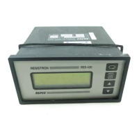
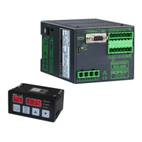
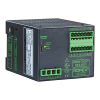
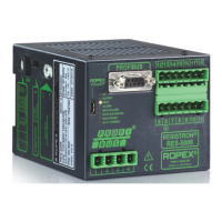
RESISTRON
®
temperature controller
Relay Kb
Load break (all-pole), e.g. in combination with the alarm
output of the temp. controller (ROPEX recommendation).
When using a series resistor RV-....-1 the relay Kb
shall be installed.
Impulse Transformer
Designed according to EN 61558 (isolating transformer
with reinforced insulation). Connect core to ground.
Use transformers with a one section bobbin. The
power, duty cycle and voltage values must be deter-
mined individually according to the application ( ROPEX
Application Report and "Accessories" leaflet for impulse
transformers).
Wiring
The wire cross-sections depend on the application
( ROPEX Application Report).
Wires must always be twisted (min. 20 turns/meter).
These wires must be twisted (min. 20 turns/meter)
if several control loops are laid together ("crosstalk").
Twisting (min. 20 turns/meter) is recommended to
improve EMC.