Controller functions
Page 32 RES-403 Version 1
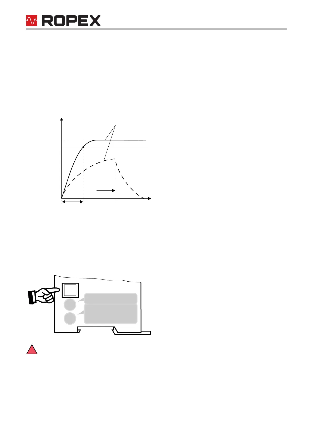
6.9 Heatup timeout
(as of October 2005)
An additional heatup timeout can be activated in the ROPEX visualization software ( section 6.10 "Diagnostic
interface/visualization software (as of October 2005)" on page 32).
This timeout starts when the START signal is activated. The RES-403 then monitors the time required for the
ACTUAL temperature to reach 95% of the SET temperature. If this time is longer than the parameterized time, the
corresponding error code (304) is indicated and the alarm relay is switched ( section 6.12 "Error messages" on
page 34).
6.10 Diagnostic interface/visualization software (as of October 2005)
An interface with a 6-pole Modular Jack (RJ-12) is provided for system diagnostics and process visualization. This
interface allows a data connection to be set up to the ROPEX visualization software using the ROPEX communi-
cation interface CI-USB-1.
Only a ROPEX comunication interface is allowed to be connected to the diagnostic interface.
Connecting another device (e.g. a telephone cable) could result in malfunctions or damage to the
controller.
The ROPEX visualization software is described in a separate document.
Set
95% of Set
Actual value
Time
Heatup time Alarm
304
Timeout
5
1
2
3
4
7
8
DIAG