Page 2 UPT-606
Contents
1 Safety and warning notes . . . . . . . . . . . . . . 3
1.1 Use . . . . . . . . . . . . . . . . . . . . . . . . . . . 3
1.2 Heating element . . . . . . . . . . . . . . . . . 3
1.3 Impulse transformer . . . . . . . . . . . . . . 3
1.4 Current transformer PEX-W2/-W3 . . . . 3
1.5 Line filter . . . . . . . . . . . . . . . . . . . . . . . 3
1.6 Standards / CE marking . . . . . . . . . . . 4
1.7 Warranty provisions . . . . . . . . . . . . . . . 4
2 Application . . . . . . . . . . . . . . . . . . . . . . . . . . 4
3 System description . . . . . . . . . . . . . . . . . . . 5
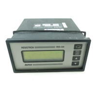
3.1 Temperature controller . . . . . . . . . . . . 5
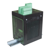
3.2 Current transformer . . . . . . . . . . . . . . . 6
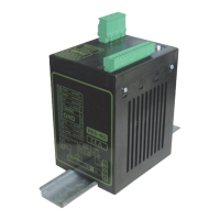
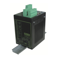
3.3 Booster . . . . . . . . . . . . . . . . . . . . . . . . 6
4 Accessories and modifications . . . . . . . . . 6
4.1 Accessories . . . . . . . . . . . . . . . . . . . . . 6
4.2 Modifications (MODs) . . . . . . . . . . . . . 7
5 Technical data . . . . . . . . . . . . . . . . . . . . . . . 8
6 Dimensions . . . . . . . . . . . . . . . . . . . . . . . . 10
7 Installation . . . . . . . . . . . . . . . . . . . . . . . . . 10
7.1 Installation steps . . . . . . . . . . . . . . . . 10
7.2 Installation procedure . . . . . . . . . . . . 10
7.3 Power supply . . . . . . . . . . . . . . . . . . . 12
7.4 Line filter . . . . . . . . . . . . . . . . . . . . . . 13
7.5 Current transformer PEX-W3 . . . . . . 13
7.6 Wiring diagram (standard) . . . . . . . . . 14
7.7 Wiring diagram with booster
connection . . . . . . . . . . . . . . . . . . . . . 15
8 Startup and operation . . . . . . . . . . . . . . . . 16
8.1 View of the controller . . . . . . . . . . . . . 16
8.2 Controller configuration . . . . . . . . . . . 16
8.3 Heating element . . . . . . . . . . . . . . . . 18
8.4 Startup procedure . . . . . . . . . . . . . . . 19
9 Controller functions . . . . . . . . . . . . . . . . . 21
9.1 Indicators and controls . . . . . . . . . . . 21
9.2 PROFIBUS communication „up to SW-
Rev 015“/“as of SW-Rev 100“ . . . . . . 23
9.3 Device master file (GSD) . . . . . . . . . . 23
9.4 PROFIBUS protocol . . . . . . . . . . . . . 23
9.5 Input data . . . . . . . . . . . . . . . . . . . . . . 26
9.6 Output data . . . . . . . . . . . . . . . . . . . . 28
9.7 Parameter data . . . . . . . . . . . . . . . . . 30
9.8 DPV1 protocol extension
(as of GSD Version v2.0) . . . . . . . . . . 35
9.9 Temperature indication (actual value
output) . . . . . . . . . . . . . . . . . . . . . . . . 38
9.10 Booster connection . . . . . . . . . . . . . . 38
9.11 Diagnostic interface/visualization
software
(as of software revision 100) . . . . . . . 39
9.12 System monitoring/alarm output . . . . 39
9.13 Error messages . . . . . . . . . . . . . . . . . 40
9.14 Fault areas and causes . . . . . . . . . . . 45
10 Factory settings . . . . . . . . . . . . . . . . . . . . . 46
11 Maintenance . . . . . . . . . . . . . . . . . . . . . . . . 47
12 How to order . . . . . . . . . . . . . . . . . . . . . . . . 48
13 Index . . . . . . . . . . . . . . . . . . . . . . . . . . . . . . 49