Do you have a question about the Ropex CIRUS UPT-640 and is the answer not in the manual?
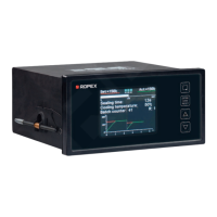
The CIRUS UPT-640 (as of SW 100) is a sophisticated temperature controller designed for heatsealing applications, particularly those involving impulse heatsealing. This device is a key component in an ULTRA-PULSE system, which is responsible for all heat management functions, including controlling the temperature of the heating element and ensuring that the highly dynamic impulse heatsealing method is accurately timed.
The UPT-640 controller manages the heating element temperature by measuring the current and voltage at a high sampling rate (line frequency). It compares this with the set point, and if there is a difference, it adjusts the heating current with the help of a phase angle-controlled transformer. This ensures precise temperature control. The basic design of the overall system involves optimizing all components in the control loop for efficient and reliable performance.
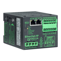
The controller features an optimized control algorithm, including functions such as "AUTOCAL" (automatic zero calibration), "TIMER" functions, "RELEASE IMPULSE," and "ALARM" with fault diagnosis. It also includes a microprocessor-based technology that allows for an easy-to-read, 4-line, multilingual display, visualizing all measured parameters and states. The controller can interact with external controllers (PLC, IPC, etc.) via analog inputs and outputs.
The UPT-640 can be used in three ways for heatsealing temperature setting:
The relationship between the applied voltage and the SET temperature is linear. The voltage values range from 0VDC to 0°C, and 10VDC to 300°C or 500°C (depending on the controller configuration). If an external heatsealing temperature (analog input, terminals 20+23) and an internal heatsealing temperature (step 101) are specified simultaneously, the higher of the two temperatures is used and indicated in the home position.
The maximum value of the setting range is limited either by the maximum value specified with step 206 in the Configuration menu or by the heatsealing band type/temperature range set with step 205. The set point that is selected for the heatsealing temperature must be greater than 40°C. If not, the heatsealing band will not be heated up when the "START" signal is activated or the "HAND" key is pressed. The set heatsealing temperature is displayed in the main menu once it has been entered.
If the heatsealing temperature is specified via the analog input at terminals 20+23, the external voltage must be activated at least 100ms before the heatsealing process starts. If not, the heatsealing temperature will not reach the required value.
The UPT-640 also provides temperature indication and actual value output. The actual temperature value indicates the current ACTUAL temperature as a 0...10VDC analog voltage. A fixed 10VDC reference voltage is output at the actual value output.
The automatic zero calibration (AUTOCAL) function is used to adjust the zero point manually on the controller. The "AUTOCAL" function matches the controller to the current and voltage signals that are present in the system. This function can be activated in two ways:
The heatsealing impulse (ambient temperature) of the heatsealing bar(s) is currently valid for calibration can be set beforehand in the 0...40°C range using the "UP" and "DOWN" keys. The zero point is calibrated in the factory to 20°C. The automatic calibration process takes around 10...15 seconds. The heatsealing band is not heated until the calibration process has finished. The message "Calibration - please wait..." appears on the display while the "AUTOCAL" function is executed. The actual value output (terminals 20+24) is set to 0...3°C (corresponds to app. 0VDC) for the duration of the calibration process. If the temperature of the heatsealing band varies on controllers as of software revision 100, the "AUTOCAL" function is executed a maximum of three times. If the function still cannot be terminated successfully, an error message appears.
The "START" signal (HEAT) is used to initiate the heatsealing process. The heating process is activated by means of the "START" signal in different ways, depending on the time control status (timer function). When the "START" signal is activated, the controller immediately sets the heatsealing band to the required temperature. It remains at this temperature until the heatsealing is activated. This process can also be started independently of the "START" signal by pressing the "HAND" key while the display is in the home position.
The time control (timer function) is active when the "START" signal starts the internally parameterized timeout. The time at which the heatsealing band begins to heat up depends on the setting of this parameter. The "START" signal must be deactivated again before the next timeout is activated. Pressing the "HAND" key while the display is in the home position causes the heatsealing band to start heating up immediately. The internal timeout is not started. The "START" signal can be activated in two ways:
The "RESET" signal is used to reset the CIRUS temperature controller UPT-640 (as of SW 100) by means of an external "RESET" signal at terminals 20+26. A heatsealing cycle is aborted if one is in progress. No more measuring impulses are generated. An error message is reset if one is present.
The correction factor Co function corrects the UPT-640 controller to be adapted to the real conditions of the machine type of UPT heating element, impulse transformer specification, length of connecting wires, cooling, etc. This function proceeds as follows to determine the optimum correction factor Co (setting in step 6):
Slowly increase the correction factor, starting either with the lowest value (50%) or with the value recommended in the ROPEX Application Report. The minimum value is 25%. The indicated hold value, set temperature, and the actual temperature or the heatsealing temperature are changed.
The maximum starting temperature function sets the maximum permissible actual value at the start time. The value is determined by the controller at the start of each impulse and compared with the value set in step 224. This function serves to monitor the cooling circuit. If the cooling system is intact, the tool is cooled down according to curve 1). If the cooling system is faulty, it is cooled down according to curve 2). Because the water is no longer cooled, as a result, the temperature is always at least the value set with this menu step. In this case, the controller ignores the next heating command and reports an alarm. The corresponding error code 205 is indicated and the fault output is switched.
The maximum value of the setting range is limited either by the maximum value specified with step 206 in the Configuration menu or by the heatsealing band type/temperature range set with step 205.
The hold mode function displays the actual temperature in the home position. The following settings are possible:
The "HAND" key function can be configured with step 213 in the Configuration menu. The display is in home position. This prevents the heatsealing bands from being heated if the "HAND" key is pressed inadvertently. The following settings are possible:
The temperature unit can be set to Celsius or Fahrenheit. As of software revision 103, the unit for temperature indication and value selection can be switched between °C (Celsius) and °F (Fahrenheit).
The Configuration menu can be disabled or enabled by pressing the "MENU" key for 2.0seconds while the power-up message is displayed. The display then shows a message confirming that the disable function has been activated. The display then shows a message confirming that the disable function is active for 3.0seconds before returning to the home position. The Configuration menu remains disabled until the disable function is canceled again. To do so, repeat the above procedure (press the "MENU" key for 2.0seconds while the power-up message is displayed). The display then shows a message confirming that the disable function has been activated. In the factory setting, the Configuration menu is not disabled.
The UPT-640 (as of SW 100) controller has a connection for an external switching amplifier (booster as standard). This connection (at terminals 1+2) is necessary for high primary currents (continuous current > 5A, pulsed current > 25A). The switching amplifier should be connected as described in section 7.7 "Wiring diagram with booster connection" on page 16. No settings are required in the menu.
The time control (timer function) is activated with step 209 [26] in the Configuration menu. There are two possible settings in this menu:
If time control is on, activating the "START" signal starts the internally parameterized timeout. This timeout comprises:
The timeout of the internal time control (timer function) can be interrupted by switching off the controller. It can also be interrupted by deactivating the "START" signal if time control "ON with START monitoring" is configured. If the display is in the home position, the individual timeouts can be monitored there. The remaining heatsealing time is indicated on the display in the form of a countdown at the end of the heatsealing phase. A direction arrow indicates the active process.
The starting delay can be set in the range from 0 to 9.99s. The factory setting is 0.0s. The progress of the calibration process is indicated by a counter on the display (approx. 10...15s). A voltage of app. 5VDC appears at the same time as the actual value output (terminals 20+24). If an ATR-X is connected, it indicates 0...1°C. When the zero point has been calibrated, the display is reset to the home position and 20°C is indicated as the actual value (a voltage of 0.66 VDC (for the 300°C range) or 0.4 VDC (for the 500°C range, equivalent to 20°C appears at the actual value output. If an ATR-X is connected, it must be set to "Z" (20°C). If the zero has not been calibrated successfully, an error message indicates error codes 104...106, 211. In this case the controller configuration is incorrect.
The heatsealing time can be set in the range from 0 to 99.9s. The factory setting is 0.1s. The heatsealing time is controlled by the "START" signal (24VDC signal applied to terminals 3+4 or contact applied to terminals 2+7). The duration of the heatsealing time is equal to the active time of the "START" signal.
The cooling mode can be set with step 210 in the Configuration menu. The following settings are available:
The cooling value can be set with step 105 in the Settings menu. The cooling parameters (only if time control is active) are:
The relay K1 function can be set with step 212 in the Configuration menu. The following settings are available:
The "Output 1" signal is available at terminals 20+21 as a digital control signal. If time control (timer function) is active, the switching output at terminals 20+21 ("Output 1") can be parameterized in the same way as relay K1.
The release impulse function allows film sticks to the heating element after the heatsealing process, it can be released by subsequently applying a short heat impulse and simultaneously tautening it. The release impulse can be generated in various ways, to enable it to be applied at exactly the right instant in the heatsealing sequence. The temperature and duration of this impulse can be set individually.
The release impulse temperature can be set in step 115 or the analog input (terminals 23+20). The release impulse duration can be set in step 117. The release impulse is not generated if the temperature and duration (step 115 and 117) are set to "0".
The system monitoring/alarm output function is to increase operating safety and to avoid faulty heatsealing. The controller incorporates special hardware and software features that facilitate selective fault detection and diagnosis. Both the external wiring and the internal system are monitored. These features crucially support the system owner in localizing the cause of an abnormal operating state. A system fault is reported or differentiated by means of the following elements:
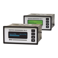
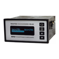
The UPT-640 is designed for ease of use with a clear display and intuitive menu navigation. The "MENU" key is used for advancing to the next menu step or switching menu. A short press (< 1 sec.) returns to the previous position, while a long press (> 2 sec.) returns to the home position. The "ENTER" key saves values, activates manual mode, and resets alarms. The "UP" and "DOWN" keys are used for setting values, with short presses for slow changes and long presses for fast changes.
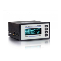
The display provides a power-up message, company name, software ID number, and controller type. In the home position, the display shows the set heatsealing temperature, measured ACTUAL temperature, heatsealing parameters, and cooling parameters.
Navigation through the menus is straightforward. In a fault-free state, the "MENU" key allows navigation through various menu steps and levels. In case of an alarm, the "ENTER" key can be pressed to acknowledge the fault, and the "RESET" key can be pressed to reset the alarm. The "AUTOCAL" function can be activated from the alarm menu.
The menu structure is divided into "Settings" and "Configuration" menus, allowing users to customize various parameters such as heatsealing temperature, starting delay, heatsealing time, cooling value, hold mode, AUTOCAL, correction factor, release temperature, release delay, release duration, language, factory settings, alloy/TCR, maximum temperature, set point reached, set point exceeded, time control, cooling mode, relay K1 function, lock "HAND" key, cycles, alarm relay, analog output, starting temperature, heatup timeout, measuring impulse length, autocomp, "Output 1", starting temperature, and temperature unit.
The controller requires no special maintenance. Regular inspection and/or tightening of the terminals, including the terminals for the winding connections on the impulse transformer, is recommended. Dust deposits on the controller can be removed with dry compressed air.
Factory settings can be restored via the "Factory settings" menu (step 202 in the Configuration menu). This option restores the menu values listed in section 10 "Factory settings" on page 51. These values correspond to the factory settings with which the controller was delivered.
Customer settings can be saved and restored. The controller factory settings can be specified or restored with step 202 in the Configuration menu. You can also store customer settings in addition to the ROPEX settings.
The controller provides extensive system monitoring and alarm outputs to facilitate fault diagnosis. Error messages are displayed on the screen, and an alarm relay provides a physical output. The error codes are detailed in the manual, along with possible causes and recommended actions. For instance, an "ALARM: Heating elem. ERROR CODE: 103 RESET KEY" indicates a fault in the heating element.
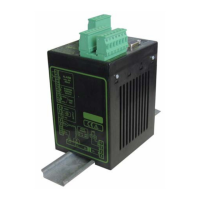
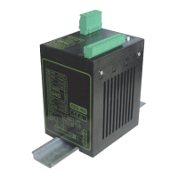
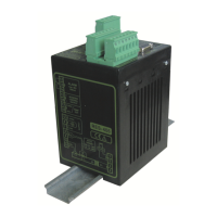
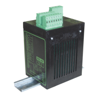
The device is designed for easy installation in a front panel cutout, with dimensions provided for precise fitting. Connecting cables are specified for rigid or flexible wires, and ferrules are recommended for proper electrical contact in the terminals.
The UPT-640 is designed for long-term reliability in industrial environments, with robust construction and comprehensive self-diagnostic capabilities to ensure continuous operation and minimize downtime.
| Brand | Ropex |
|---|---|
| Model | CIRUS UPT-640 |
| Category | Temperature Controller |
| Language | English |