EasyManua.ls Logo

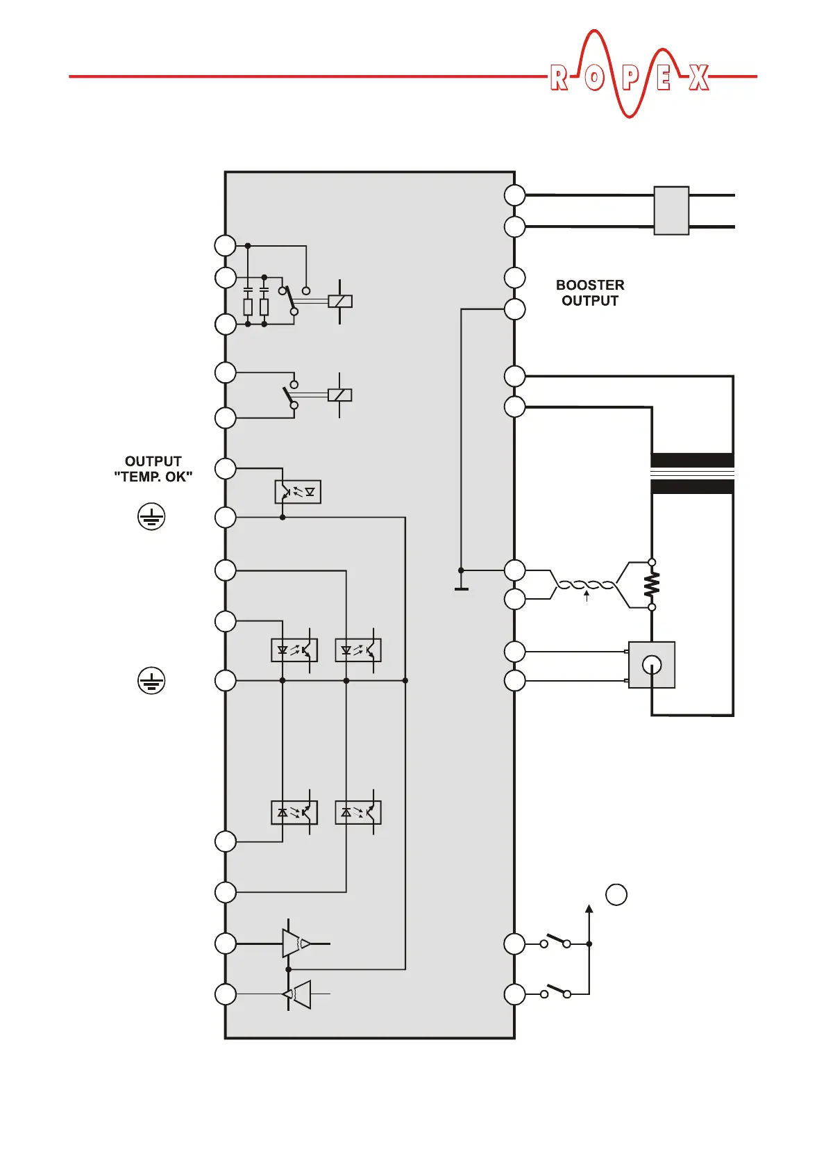
Ropex CIRUS UPT-640 - Wiring Diagram (Standard)

Ropex CIRUS UPT-640
55 pages
Print Icon
To Next Page IconTo Next Page
To Previous Page IconTo Previous Page
Loading...
Installation
UPT-640 (as of SW 100) 15
7.6 Wiring diagram (standard)
4
3
5
6
20
21
22
26
24
25
23
15
14
116
17
2
18
K1
2x 47nF/560R
UPT-640
(also with MOD 01)
AUTOCAL
with 24VDC signal
RESET
with 24VDC signal
+
+
TEMP. IN
0 - 10VDC
TEMP. OUT
0 - 10VDC
8
9
12
13
10
11
19
7
START (HEAT)
with contact
START (HEAT)
with 24VDC signal
ALARM
OUTPUT
max. 30V/0,2A
RELAY K1
100VDC/1,5A
240VAC/1,5A
GND
GND
Contact closed or
opened by ALARM
(see configuration)
Ground
for 24VDC signals.
Must be grounded
externally to prevent
electrostatic
charging!
0V (Internal ground)
Terminal
2
Impuls
transformer
Remark:
Only principal diagram.
Heating/sensor elements,
impulse transformer and wiring
must be determined individually
according to the application
(see ROPEX-Application Report).
R
I
R
U
R
Current transformer
PEX-W2/-W3
LINE
Line filter LF-xx480
+
0V
RELEASE IMPULSE
(CH1)
with 24VDC signal
sec.
U
2
prim.
U
1
twisted
RELEASE IMPULSE
(CH1)
with contact
heating
element
0V
(Intern. ground)
No external
grounding
allowed!

Table of Contents