2-5
Installation
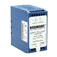
FIGURE 2-4. Tri-Loop Dimensions.
ELECTRICAL
CONSIDERATIONS
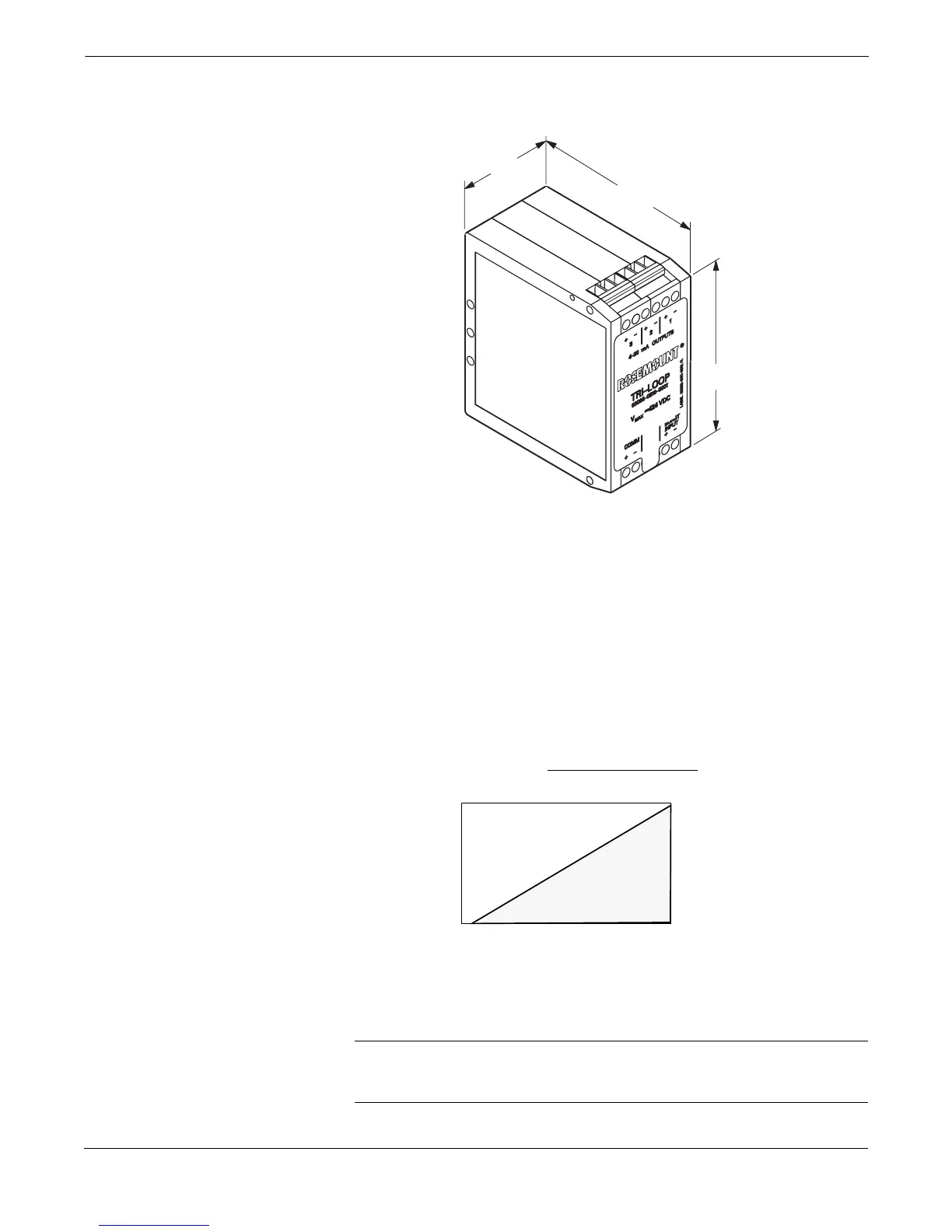
Figure 2-5 illustrates power supply load limitations for each channel of
the device. Each channel operates on terminal voltage of 11–42.4 V dc.
Channel 1 must be powered for Tri-Loop operation.
Power Supply
The dc power supply should provide power with less than 2% ripple.
The total resistance load is the sum of the resistance of the signal leads
and the load resistance of the controller, indicator, and related pieces.
NOTE
Wiring connections must be made in accordance with local or national
installation codes such as the NEC NFPA 70.
1.57
(40)
3.11
(79)
3.36
(86)
NOTE
Dimensions are in inches (millimeters).
3095-0810A01A
FIGURE 2-5. Power Supply
Load Limitations.
3051-0103A
1800
1600
1400
1200
1000
800
600
400
200
0
10 20
42.4
Load (Ohms)
30
Max. Loop Resistance = Power Supply Voltage–11.0
0.022
Power Supply Voltage, V dc
40
Operating Region