HART Tri-Loop HART-to-Analog Signal Converter
2-6
INSTALLATION
EQUIPMENT
The following equipment and tools are not provided with the HART
Tri-Loop.
• Installation tools
• Wire between the control room and the Tri-Loop
• Wire between the Model 3095 MV and the Tri-Loop
• Power supply
• IS Barrier
INSTALLATION
PROCEDURE
1. Review Installation
Considerations
1. Review the installation considerations described on pages 2-4
through 2-5 in this chapter to determine the location for the
HART Tri-Loop.
2.Mount Tri-Loop on
DIN Rail
2. Mount the HART Tri-Loop on any of the following DIN rails:
• asymmetrical 32mm G rail,
• symmetrical 35 3 7.5 mm top hat rail
• symmetrical 35 3 15 mm top hat rail.
3. Wiring
3. Make wiring connections (see Figure 2-6).
NOTES
• Wiring need not be shielded, but twisted pairs should be used for
best results.
• To ensure communication, wiring should be between 24–12 AWG
(solid or stranded) and not exceed 1,000 feet (305 meters).
a. Run wire from Tri-Loop Channel 1 to control room, and secure
using screw clamps. Be sure to observe proper polarity. Include
proper loop resistance (see page 2-5).
b. (Optional) Run wire from Tri-Loop Channel 2 to control room,
and secure using screw clamps. Be sure to observe proper
polarity. Include proper loop resistance (see page 2-5).
c. (Optional) Run wire from Tri-Loop Channel 3 to control room,
and secure using screw clamps. Be sure to observe proper
polarity. Include proper loop resistance (see page 2-5).
d. Run wire from the Model 3095MV to BURST INPUT
connections, but do not complete connections at this time.
(See Figure 2-6).
NOTE
Tri-Loop commissioning will be much faster if the Tri-Loop does not
have to compete with the Model 3095 MV burst commands. We
therefore do not recommend completing the Burst Input connections
until the Tri-Loop is commissioned (Chapter 3).
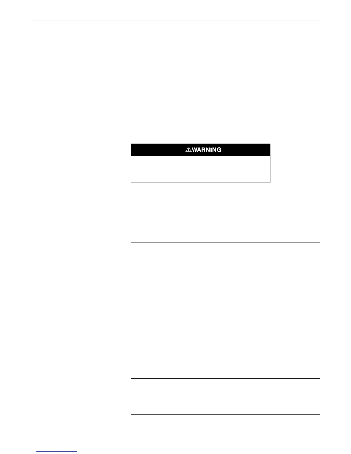
Explosions can cause death or serious injury. The HART Tri-
Loop is designed for installation in ordinary locations only.
Do NOT install the HART Tri-Loop in hazardous locations.