HART Tri-Loop HART-to-Analog Signal Converter
3-4
Configuration Procedure
The following procedure outlines the major steps needed to configure a
Tri-Loop. For more detailed information, use the Configurator on-line
help screens.
1. Double click on the HART Tri-Loop Configurator Software icon.
2. Select T
ri-Loop, Connect to Tri-Loop to display the connect
screen, then connect to a Tri-Loop.
NOTE
If you are unable to connect to a Tri-Loop, see Table 4-1 on page 4-1 for
suggestions.
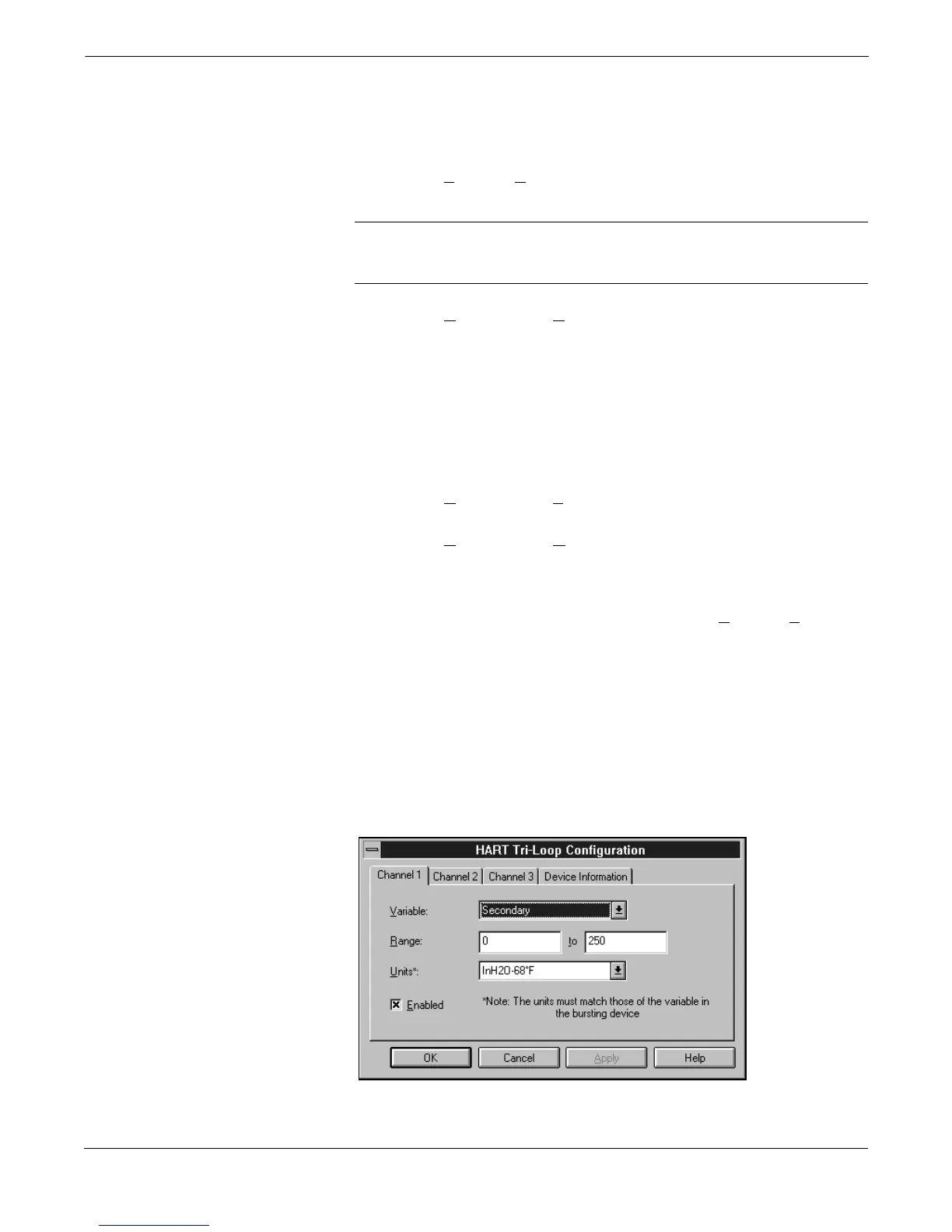
3. Select C
onfiguration, Configure Channels to display the HART
Tri-Loop Configuration Screen (Figure 3-3).
a. Click Channel 1, and select the process variable for this
channel, desired range, and
exact
Model 3095 MV units.
If required, click on the Enabled box so that the Tri-Loop
analog output will be enabled.
b. (Optional) Repeat step a for Channels 2 and 3.
c. Click device information, enter the desired tag, descriptor, and
message information, then select OK.
4. Select C
onfiguration, Save to Tri-Loop to send the configuration
to a Tri-Loop.
5. Select C
onfiguration, Open from Tri-loop to verify that the
configuration was correctly received. The Tri-Loop configuration
information will be displayed in the main window of the HART
Tri-Loop Configurator software.
6. If necessary, perform an analog output trim (T
ri-Loop, Trim
Outputs) for each enabled Tri-Loop analog output.
7. Complete the connection between the Model 3095 MV analog
output and the Tri-Loop Burst Input as illustrated in Figure 3-4.
8. Use a multimeter or the control room equipment to verify that
each new Tri-Loop channel is transmitting the Model 3095 MV
process variables.
FIGURE 3-3. HART Tri-Loop
Configuration Screen.
3095-30950702