Section
4-1
4 Troubleshooting
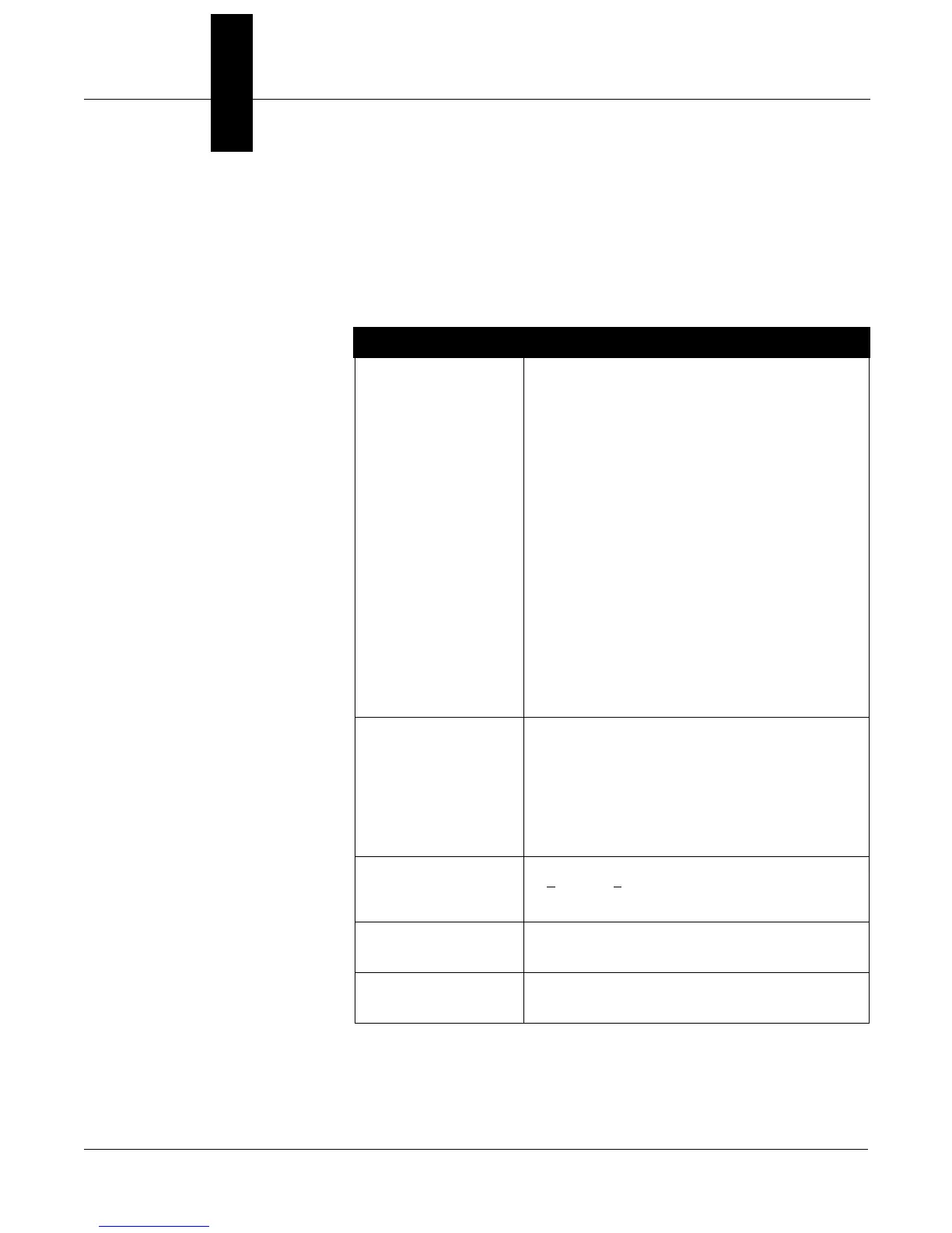
Table 4-1 provides troubleshooting suggestions for the most common
operating problems.
TABLE 4-1. Tri-Loop Troubleshooting
Table.
Symptom Corrective Action
No Communication
between the HART
Tri-Loop Configurator
Software and the Tri-Loop
LOOP WIRING
• Close both EA software and Tri-Loop Configurator software,
then restart the Tri-Loop Configurator software.
• HART protocol communication requires a loop resistance
value between 250–1100 ohms, inclusive.
• Checkfor adequate voltage to the Tri-Loop.(Channel 1 must be
powered for the Tri-Loop to operate.)
• Check for intermittent shorts, open circuits, and multiple
grounds.
• Check for capacitance across the load resistor. Capacitance
should be less than 0.1 microfarad.
TRI-LOOP SOFTWARE INSTALLATION
• Verify computer reboot followed software installation.
• Verify correct COMM port selected.
• Verify laptop computer is not in low energy mode
(certain laptops disable all COMM ports in low energy mode).
• Did you install software onto Windows NT platform?
(Configurator software will only work with Windows 3.1,
Windows for Workgroups 3.11, or Windows 95.)
• Check if HART driver was subsequently over-written during a
Model 3095 MV Engineering Assistant installation. If this has
occurred, reinstall the Configurator software.
• Check the DEVICEHIGH statement in the CONFIG.SYS
statement as explained in the Configurator “readme” file.
Burst Commands not
received from Model 3095
MV
• Verify the Model 3095 MV is set to Burst Command 3.
• Checkfor adequate voltage to the Tri-Loop.(Channel 1 must be
powered for the Tri-Loop to operate.)
• Check for intermittent shorts, open circuits, and multiple
grounds.
• HART protocol communication requires a loop resistance
value between 250–1100 ohms, inclusive. Typically, the
required resistance is installed during the Model 3095 MV
installation.
Tri-Loop Channel is in
Alarm
• Use the HART Tri-Loop Configurator, and select
D
iagnostics, Error Info to determine the cause of the alarm.
For information on any error message, use the Configurator
on-line help files.
Channel 1 operates
correctly, but Channel 2
(or Channel 3) does not
• Check for proper loop resistance for the channel. Each
channel must have it’s own power supply and required loop
resistance (see page 2-5).
Win32S error
Runtime Error!
• If you receive a Win32s or Runtime error, remove Win32s and
reinstall the Configurator software as explained in the
Configurator “readme” file.