Ultripower User Guide (v4.0) Monitoring the Ultripower • 27
Monitoring the Ultripower
You can monitor the Ultripower from the front panel LEDs, the rear panel LEDs, and via the read-only fields in
DashBoard. Each location reports the status on a specific feature of the Ultripower.
Monitoring via the Front Panel LEDs
The Ultripower front panel includes LEDs for each power supply to indicate if the unit is operating normally and
whether the power supplies are functional.
For More Information on...
• the location of the LEDs on the front panel, refer to the section “Front Panel Overview” on page 13.
Power Supply Module LEDs
There are three status LEDs per PSU module to indicate the operation status of Ultripower. Table 6.1 outlines the
LEDs available for each power supply module.
Monitoring via the Rear Panel LEDs
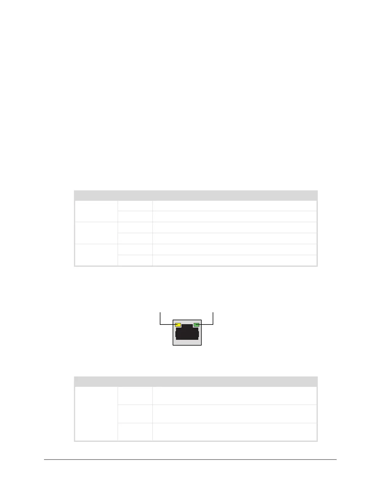
The Ultripower rear panel includes LEDs on the ETHERNET RJ45 port. (Figure 6.1)
Figure 6.1 ETHERNET Port LEDs
Table 6.1 Front Panel — Power Supply Module LEDs
LED Status Description
DC On The module is supplying DC voltage to the system.
Off The module is not supplying DC voltage to the system.
AC On A valid AC voltage supply is connected to the rear panel.
Off No AC voltage is present.
FAN On The two module fans are operating correctly.
Off One or both module fans are not operating correctly.
Table 6.2 Rear Panel — ETHERNET LEDs
LED Status Description
LINK
/ACTIVITY
Green When lit solid green, this LED indicates an invalid link is
detected on the RJ45 port or an absence of communication.
Flashing
Green
When flashing green, this LED indicates communication activity
is occurring on the RJ45 port.
Off When unlit, this LED indicates an invalid link is detected on the
RJ45 port or an absence of communication.
LINK / ACTIVITY LEDPORT SPEED LED