Ultripower User Guide (v4.0) Hardware Overview • 13
Hardware Overview
This chapter presents information on the Ultripower front and rear panels.
Front Panel Overview
The Ultripower front panel enables you to monitor the power supplies via the LEDs for each slot.
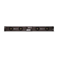
Figure 3.1 Ultripower — Front Panel
1. Slot 1 Power Supply Module
The Slot 1 Power Supply Module provides power to the four DC outputs. If a PSU module is present and
operating in Slot 2, the load is distributed between the operating modules.
2. Slot 1 Status LEDs
The Slot 1 Status LEDs monitor the Slot 1 PSU power supply and status. Refer to Table 6.1 for details.
3. Slot 2 Power Supply Module
The Slot 2 Power Supply Module provides power to the four DC outputs. If a PSU module is present and
operating in Slot 1, the load is distributed between the operating modules.
4. Slot 2 Status LEDs
The Slot 2 Status LEDs monitor the Slot 2 PSU power supply and status. Refer to Table 6.1. for details.
Rear Panel Overview
The rear panel provides a support structure for connecting power inputs, power outputs, and to your facility
network.
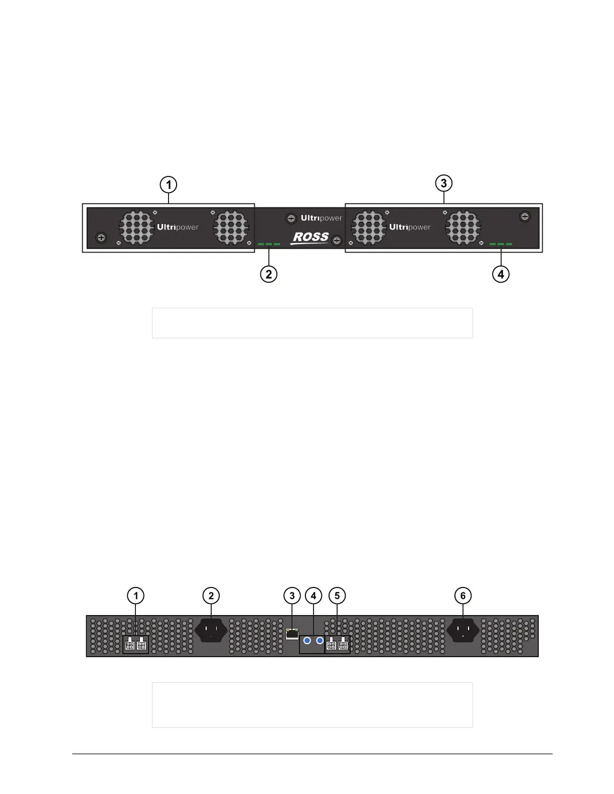
Figure 3.2 Ultripower — Rear Panel Overview
1) Slot 1 Power Supply Module 3) Slot 2 Power Supply Module
2) Slot 1 Status LEDs 4) Slot 2 Status LEDs
1) PSU OUT Ports 1 and 2 4) Reset and Restart Buttons
2) PSU IN Port 2 5) PSU OUT Ports 3 and 4
3) 10/00 Ethernet Port 6) PSU IN Port 1
ACDC FAN ACDC FAN
Slot
1
-PS
Slot
2
-PS
1 2
OUT
2 1
OUT
4 3
RESTART
ETHERNET
RESET