ULTRIX-FR12 Installation Guide (v4.0) Physical Installation • 23
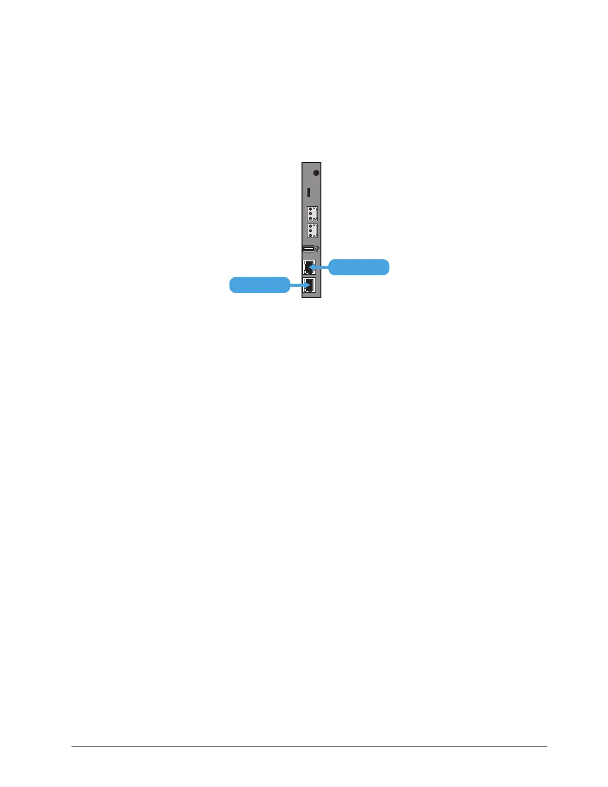
1. Locate the ENET ports on the Frame Control CPU Module of the ULTRIX-FR12 rear panel. Refer
to Figure 3 for module location.
2. To connect the primary network connection for the ULTRIX-FR12 router:
a. Connect one free end of a standard CAT 5/5e/6 Ethernet cable to a free port of the network
hub.
b. Connect the other end of the same cable to the ENET 1 port on the rear of the ULTRIX-FR12
router.
Figure 4 ULTRIX-FR12 — Network Connections
3. To connect the redundant network connection for the ULTRIX-FR12:
a. Connect one free end of a second straight through CAT 5/5e/6 cable to a free port of the
network hub.
b. Connect the other end of the same cable to the ENET 2 port on the rear of the ULTRIX-FR12.
ENET 1 ENET 2
ALARMLTC micro SD
R-OUT
ENET 2
ENET 1