ULTRIX-FR12 Installation Guide (v4.0) Cabling Your Router • 33
Cabling Your Router
This chapter provides instructions on how to connect the ULTRIX-FR12 to a video reference signal,
cabling for a Multiviewer Head, and connecting to source and destination devices.
Cabling the ALARM Port
The ALARM port is a normally closed relay output. The relay output is open when the ULTRIX-FR12
is powered on and there are no alarms present. Table 6 outlines the conditions that will assert the
ALARM port output.
The conditions that generate an alarm are critical incidents that stop the ULTRIX-FR12 from
working. If the ULTRIX-FR12 is not supervised or at a remote site, such an alarm is used to alert
system technicians that a failure has occurred, or the alarm can be used to trigger a backup system.
Ross Video does not supply these cables.
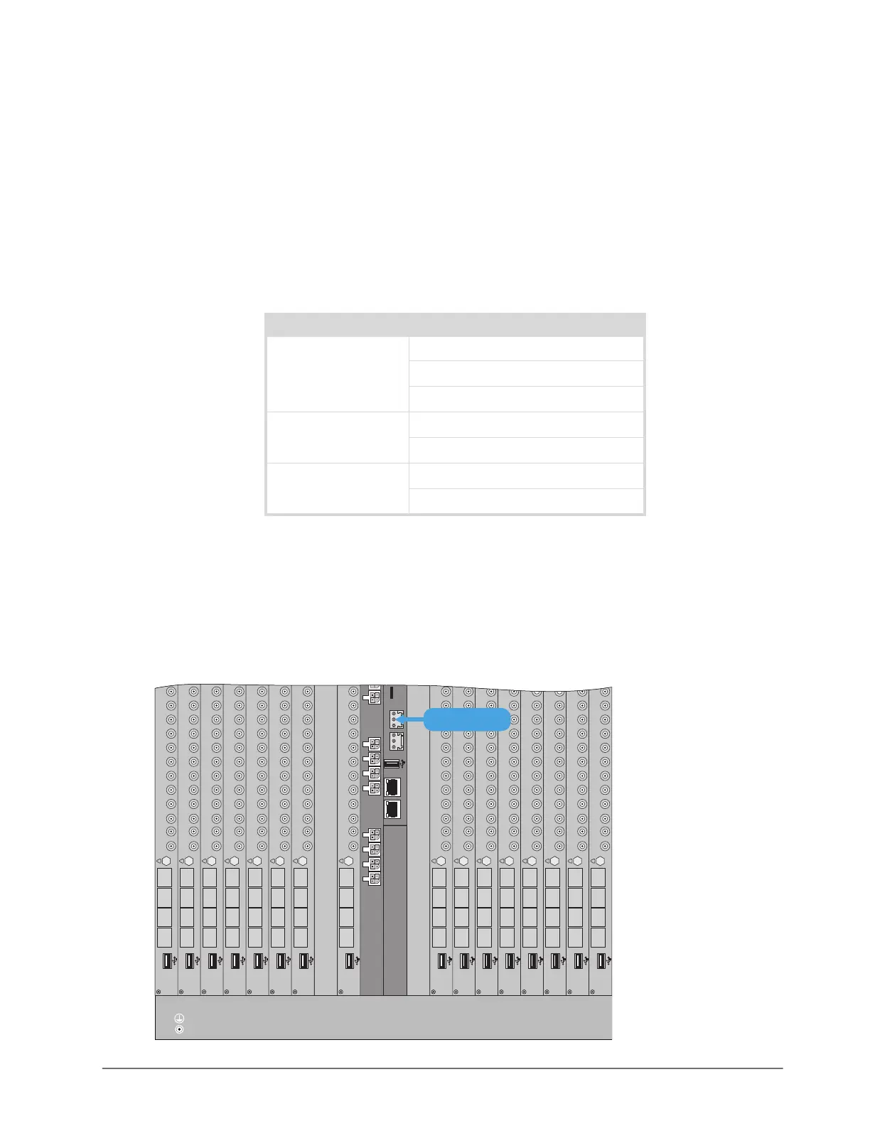
To connect to the ALARM port on the ULTRIX-FR12
1. Locate the ALARM port on the ULTRIX-FR12 back panel.
Table 6 Alarm Conditions
Component Possible Reason
Matrix Fan failure
Overheating
Power failure
I/O Blades Overheating
Power failure
Power PSU failure
PSU removed
11414
ENET 1 ENET 2
ALARMLTC micro S
234567 8 91 1011 1314151612
C DA B
Ultrix HDX-IO
!
9 101112
OUT
56781324
C DA B
Ultrix HDX-IO
!
9 101112
OUT
56781324
C DA B
Ultrix HDX-IO
!
9 101112
OUT
56781324
C DA B
Ultrix HDX-IO
!
9 101112
OUT
56781324
C DA B
Ultrix HDX-IO
!
9 101112
OUT
56781324
C DA B
Ultrix HDX-IO
!
9 101112
OUT
56781324
C DA B
Ultrix HDX-IO
!
9 101112
OUT
56781324
C DA B
Ultrix HDX-IO
!
9 101112
OUT
56781324
C DA B
Ultrix HDX-IO
!
9101112
OUT
56781324
C DA B
Ultrix HDX-IO
!
9101112
OUT
56781324
C DA B
Ultrix HDX-IO
!
9101112
OUT
56781324
C DA B
Ultrix HDX-IO
!
910111
OUT
56781324
C DA B
Ultrix HDX-IO
!
91011
OUT
56781324
C DA B
Ultrix HDX-IO
!
91011
OUT
56781324
C DA B
Ultrix HDX-IO
!
91011
OUT
56781324
C DA B
Ultrix HDX-IO
!
9101112
OUT
56781324
ALARM PORT