34 • Cabling Your Router ULTRIX-FR12 Installation Guide (v4.0)
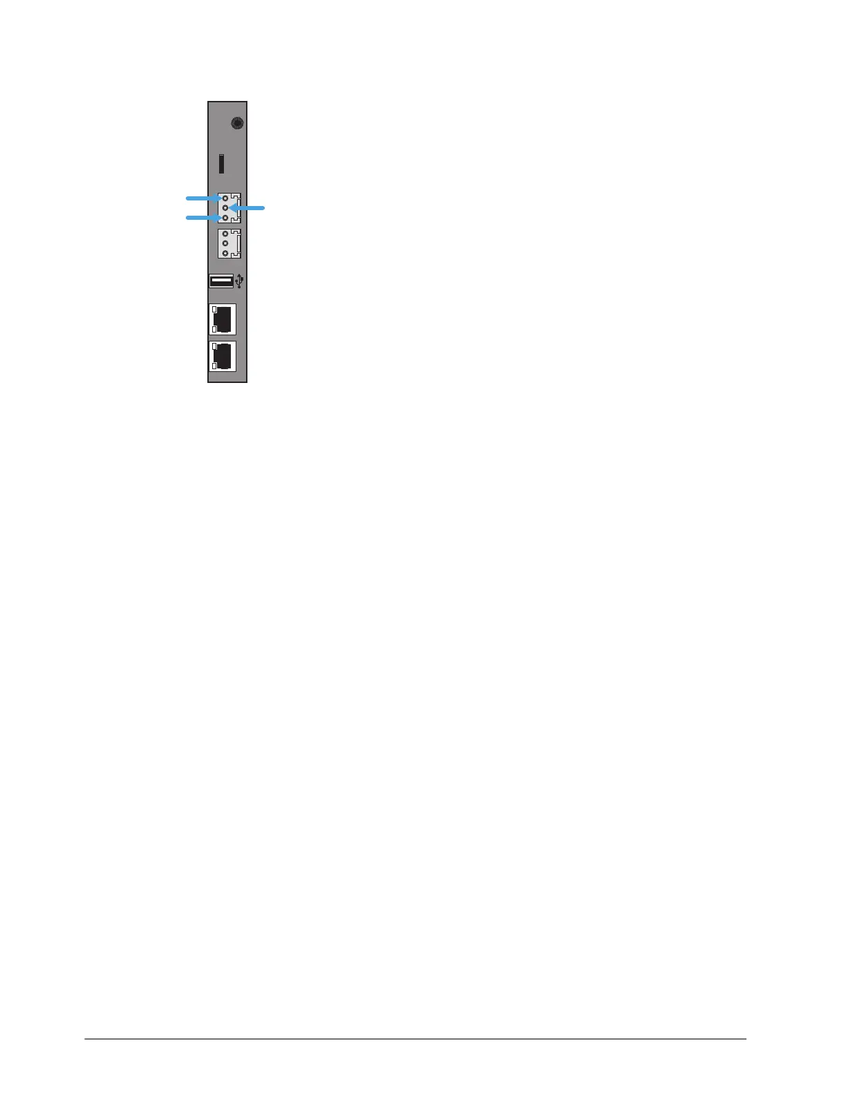
2. Wire the ALARM mating connector to match the pinout as shown in the following diagram.
3. Once the cable is wired to the connector, plug the connector into the ALARM port on the
ULTRIX-FR12 back panel.
Connecting the Video Reference Source
All ULTRIX-FR12 routers accept a video reference signal. If connected, a video references ensures
that switching occurs in the default vertical interval across all router levels. The default switching
pulse complies with SMPTE RP168 as follows:
• line 6 for SD (PAL reference)
• line 10 for SD (NTSC reference)
• line 7 for HD (1080i)
• line 7 for HD (720p)
• line 7 for 3G (1080p)
Alternatively, you can set your own custom switching point to meet the requirements of your
system. For example, if the default settings for the switching pulse occur within the data elements
of your signal, you need to assign your own switching trigger.
For More Information on...
• setting a custom switching trigger, refer to the ULTRIX-FR12 User Guide.
• supported reference formats for Frame Sync/Clean Switch, refer to “Supported FSCS Video
Formats for Conversion”.
Reference Cabling for the ULTRIX-FR12
The ULTRIX-FR12 consists of two independent reference connections (REF A, REF B). Each may be
configured for loop-through or terminating functionality. The ULTRIX-FR12 requires at least one
reference connection.
ENET 1 ENET 2
ALARMLTC micro SD
R-OUT
COMMON
CLOSED
OPEN