16
6. Turn disconnect switch to “OFF”.
7. Open top panel, move calibrate switch to
“Run”,and re-close the top panel.
8. Turn disconnect switch to “ON”
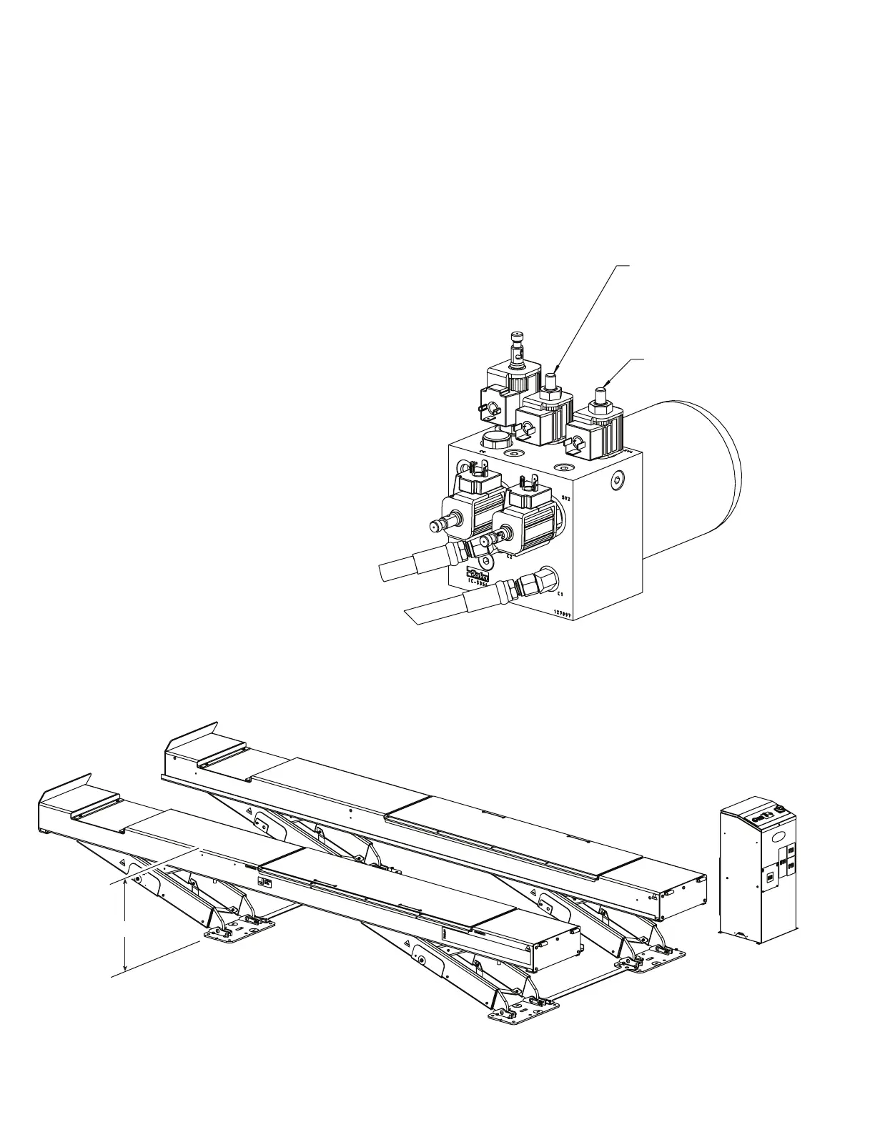
9. Raise the runways to the 5th lock position by
pressing the“RAISE” button as shown in Fig.
7 to raise both runways until the top of one
runway is approximately 42” above the top of
the base plates, Fig. 11.
10. Lower the runways onto the fifth lock position
by pressing the “LOWERTOLOCKS” button as
shown on Fig. 7.
11. Turn disconnect switch to “OFF”.
12. Open the top panel and move the toggle switch
to “CALIBRATE” then re-close top panel.
13. Turn disconnect switch to “ON”.
14. Press the“LOWERTOLOCKS”and“UP”button
simultaneously and hold for 5 seconds until a
single beep is heard.
15. Turn disconnect switch to “OFF”.
16. Open top panel and move the toggle switch to
“RUN” then re-close panel.
17. Turn disconnect switch to “ON”. Lift is now
calibrated.
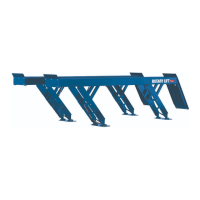
SV3 - Rotate This Knob To
Adjust Flow To The Left
Runway Cylinder (C1)
SV4 - Rotate This Knob To
Adjust Flow To The Right
Runway Cylinder (C2)
Manifold In Control Cabinet
Fig. 10
Measure Here
Fig. 11
CalibrateRunways
 Loading...


