45
11.3 Site specications
•
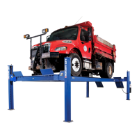
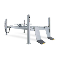
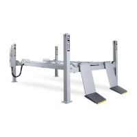
The post lift may only be installed above ground
and indoors.
•
Refer to the building plans when selecting a site.
•
When anchoring to the oor, take into account
any pipes, cables, and supply lines lying there.
•
Ensure that the load capacity of the foundation is
adequate.
•
Support surface for lift columns:
Reinforced concrete, concrete quality C20/C25
•
Floor load capacity for each lift column (34 x 23
cm): Min. 2000 kg.
•
Floor must be designed for a oor anchor.
•
Concrete dimension 6500x3800x200 mm
for SM65-60 without the area for ramps (for
example).
Do not t post lifts onto asphalt or a similar
unstable surface, since the anchor may
come loose in the oor.
•
Comply with the specied minimum distances
and clearances ( → Chapter 3.3. Work place,
danger zone):
•
Min. work area for loading and movement:
11.5m x 4.98 m.(example for SM65-60)
•
Min. distance around sides:
0.8 m, without through trafc 0.6 m
•
Min. ceiling height / lamp height:
2.032 m + overhead clearance of largest vehicle.
Take account of the max. required hall height
room height. For variants with lifting table,
also factor in the max. extension height of the
lifting table.
For wheel alignment lifts, take into account
the vehicle or alignment system
manufacturer’s specications.
• Runways must be tted straight and level. Height
tolerance ± 5 mm, max. difference between di-
agonals 6 mm.
Tighter tolerances are dened for the optional
wheel alignment kit, according to
manufacturer’s specications.
• Factor in sufcient space for the approach and
drive-off. Take drive-on ramps into account.
• Take note of the maximum bearing pressure
under the lift column. Take into account the
weight distribution and the dead load of the lift
parts.
11.4 Installation preparations
1. Provide an electrical and pneumatic outlet close
to the lift column with the control unit:
•
Electrical, according to the lift variant :
400 V (3xL+N+PE), 50HZ for standard.
Cable diameter:5x 2,5m²
Cable length: approx. 2 m
•
Pneumatic: 6...8 bar. When using a
pneumatic axle jack (Optional)
8...10 bar.
2. Level out any uneven oor areas around the
lift columns. If required, ll bearing surfaces for
lift columns with reinforced concrete (concrete
quality C20/C25).
3. Equalize slight differences in height between lift
columns using spacers or shims (optional ac-
cessories).
The 4 lift columns must be leveled exactly to
the same height
so that the runways are horizontal. This is
also important when settling the lift onto the
latch bars.
Use only original spacers or shims
( optional accessories)
Difference in diagonals<6mm
33
 Loading...