7.4) Electric system
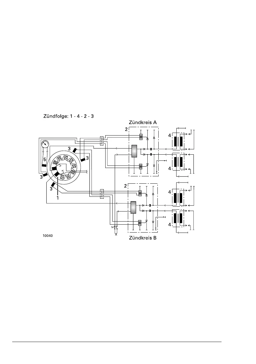
The ROTAX® 912 engine is equipped with a dual ignition unit of
a breakeless, capacitor discharge design, with an integrated
generator.
The ignition unit needs no external power supply.
Charging coils
Two independent charging coils located on the generator stator
supply one ignition circuit each. The energy is stored in capaci-
tors of the electronic modules. At the moment of ignition 2 each
of the 4 external trigger coils actuate the discharge of the ca-
pacitors via the primary circuit of the dual ignition coils.
NOTE
The trigger coil is provided for rev counter signal.
1
Charging coils
2 Electronic modules
3
Trigger coils for ignition
signal
4
Dual ignition coils
5
Trigger coil for speed
signal
Figure .4: Ignition circuit
Page 7-6
November 01/2016
BRP-Rotax Effectivity: 912 Serie
Edition 4 / Rev. 0

 Loading...


