3 x Installation
20
FA ROTEX Solaris - 08/2007
3.3.2 Connect several Sanicube hot water storage tanks
The ROTEX connection pipe system permits the parallel connection of several Solaris Sanicube to obtain large-scale installations
with and without solar heating.
By means of the Solaris storage tank extension set CON SX ( 16 01 07), 2 Solaris Sanicubes can be connected per control
and pump unit RPS3 (Fig. 3-45).
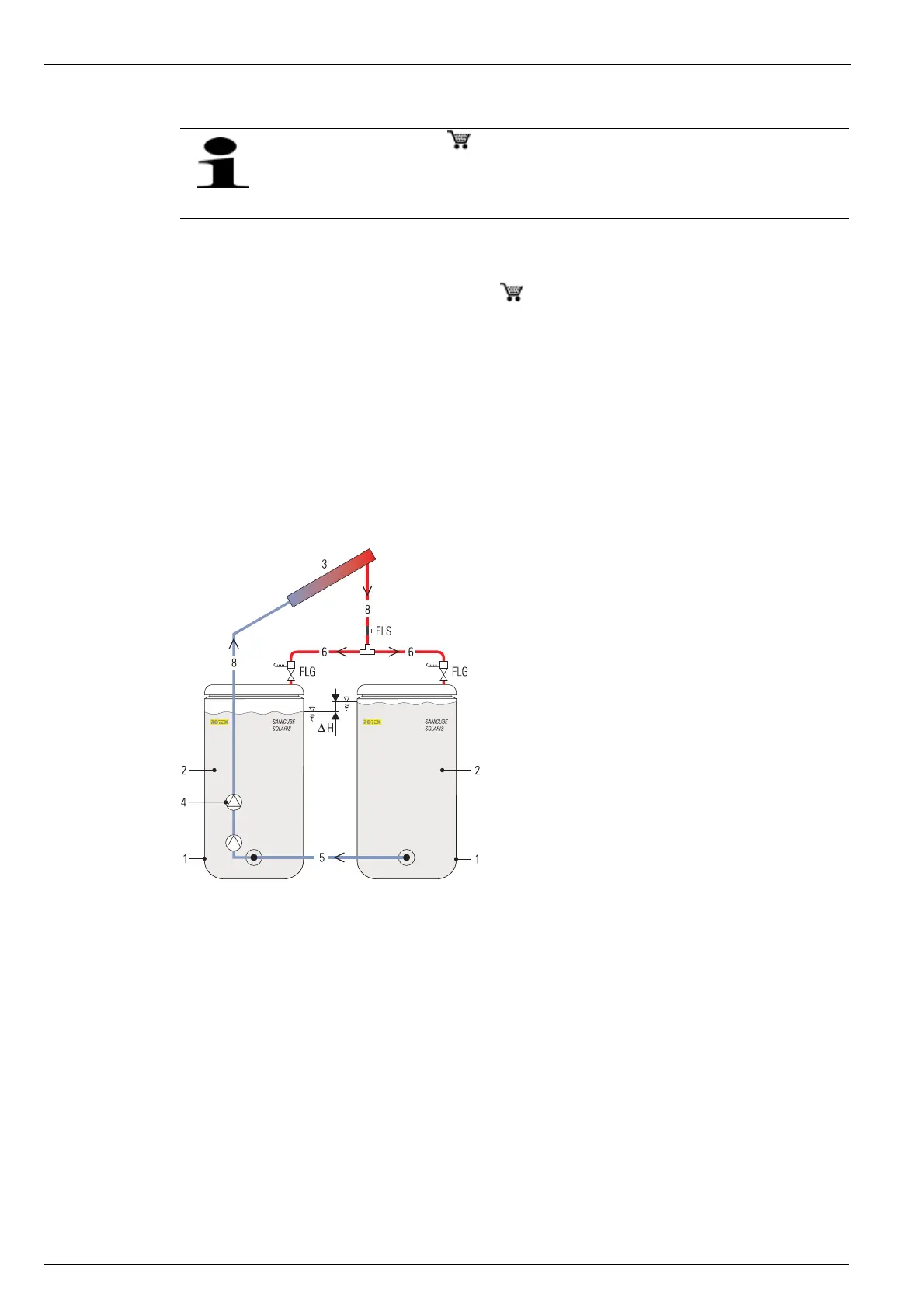
Operating principle
– The solar return flow is drawn from the common return flow pipe (Fig. 3-45, Pos.5), which connects the solar sections of
both storage tanks.
– The common return flow is pumped to the solar panel array by the RPS3 control unit (Fig. 3-45, Pos. 4).
– After being heated in the solar panel array, the water enters both storage tanks as solar feed via the feed distribution pipes
(two equally long flexible and insulated pipes, Pos.6, Fig. 3-45).
As the amount of water drawn into and circulated through the solar system can be different in the 2 Sanicubes in spite of the
matching provided by the FlowGuard valves (FLG) in the feed distribution pipes, one of the Sanicubes could overflow if there were
no common return flow pipe (Fig. 3-45, Pos. 5) as equalisation. This pipe prevents excessive level differences in the two storage
tanks.
The optional ROTEX FlowGuard ( 164102) ensures uniform filling of both Sanicubes. For this, one
FlowGuard must be installed per storage tank, with a common feed pipe to the FlowSensor.
After connecting and starting the system, the filling levels should be observed for at least 2 hours and the
FlowGuards adjusted if necessary.
1 Sanicube Solaris
2 Non-pressurised area
3 Solar panel array
4 Control and pump unit RPS3
5 Return flow connection pipe
(non-pressurised area)
6 Solaris feed distributor
7 Solaris return flow pipe
8 Solaris feed pipe
Δ
H Difference in level in non-pressurised
storage tank area
FLS Flow sensor
FLG FlowGuard
Fig. 3-45 Operating principle of the common return flow pipe